Appendix A
-
136
-
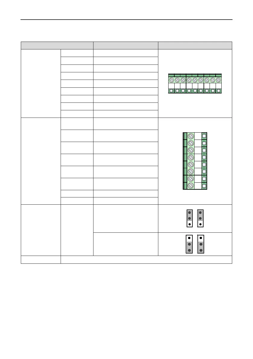
A.5.3 Differential Input PG Card (MD38PG1)
Table A-11 Terminal descriptions of MD38PG1
Terminal Function Description Terminal Arrangement
CN2
A+ Encoder output signal A positive
J3
A+ A- B+ B- Z+ Z- COM PE
+5V
A- Encoder output signal A negative
B+ Encoder output signal B positive
B- Encoder output signal B negative
Z+ Encoder output signal Z positive
Z- Encoder output signal Z negative
5V Encoder 5V/100mA power supply
COM Power ground
PE Shield connecting point
CN6
OA+
Encoder frequency dividing output
signal A positive
OA- OB+ OB- OZ+ OZ-
COM
OA+
PE
OA-
Encoder frequency dividing output
signal A negative
OB+
Encoder frequency dividing output
signal B positive
OB-
Encoder frequency dividing output
signal B negative
OZ+
Encoder frequency dividing output
signal Z positive
OZ-
Encoder frequency dividing output
signal Z negative
COM Power ground
PE Shield connecting point
CN3, CN4
"pulse +
direction"
function
Supporting the "pulse + direction"
function
Pulse signal connected to phase A,
direction signal connected to phase
B
CN3 CN4
Not supporting the "pulse +
direction" function (default setting)
CN3 CN4
CN1 18-pin FFC interface, connecting to J4 on the control board of the AC drive

 Loading...