3 Installation and Wiring
-
40
-
3
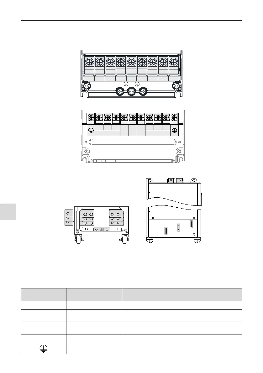
3.2.2 Functions of Main Circuit Terminals and Precautions
1. MD500 series Main Circuit Terminals
Main Circuit Terminals
Figure 3-27 Terminal arrangement in MD500T0.4GB to MD500T15GB
R S T
POWER
U V W
MOTOR
BR (+) (-)
Figure 3-28 Terminal arrangement in MD500T18.5G(B) to MD500T160G
(Front view) (Side view)
Figure 3-29 Terminal arrangement in MD500T200G(-L) to MD500T450G(-L)
Table 3-4 Description of the drive terminals
Terminal Name Description
R, S, T Three-phase supply input Connected to three-phase power supply.
(+), (-) DC bus terminals
Connected to external braking unit (MDBUN) with AC drive units
of 90 kW and above.
(+), BR Braking resistor connection
Connected to external braking resistor for AC drive units of 75
kW and below.
U, V, W AC drive outputs Connected to a three-phase motor.
Ground (PE) Grounding connection.

 Loading...