3 Installation and Wiring
-
39
-
3
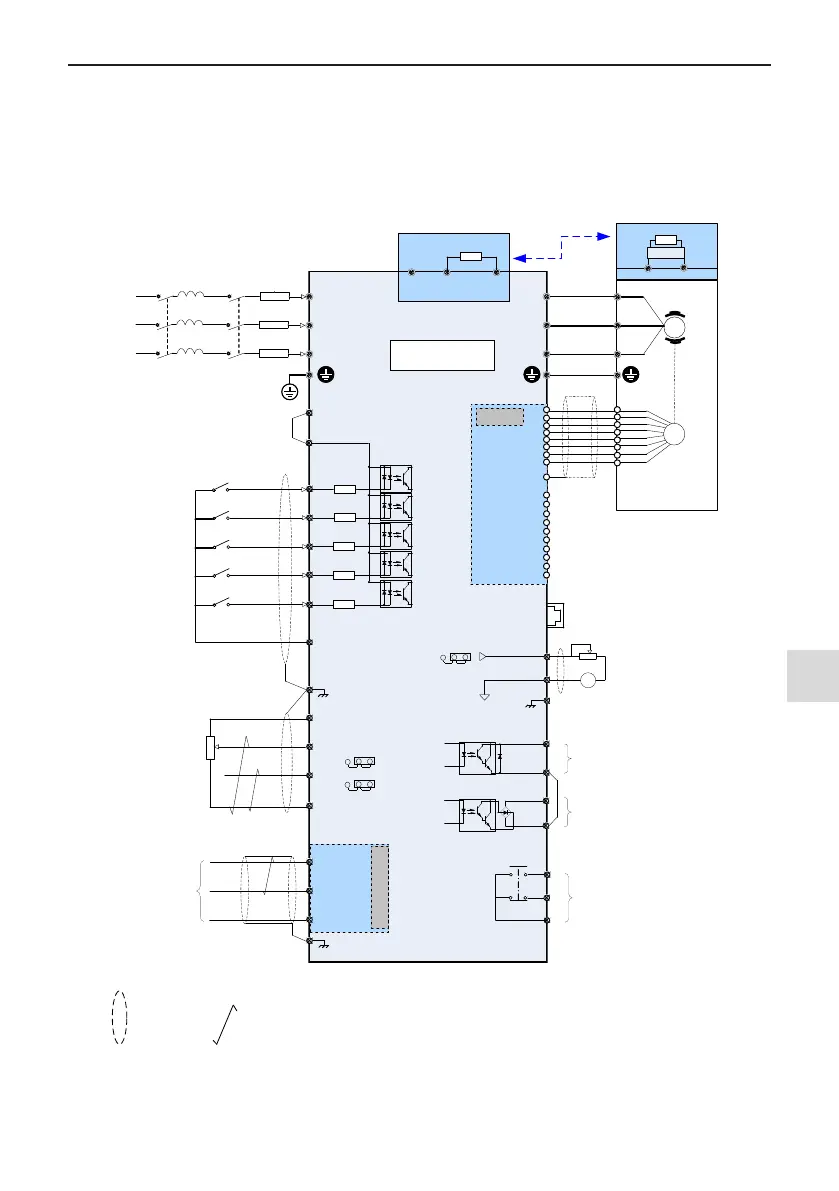
3.2 Wiring
3.2.1 Standard Wiring Diagram
As shown in the following gure, the wiring part at the 0.4kW~75kW marked by double-headed arrow in 0.4 to
75 kW and 90 to 450 kW models is different.
R
S
T
U
V
W
+24V
OP
DI1
DI2
DI3
DI4
DI5
COM
+10V
AI2
GND
485-
485+
GND
AI1
T/C
T/B
T/A
FM
COM
DO1
CME
AO1
GND
L
1
L2
L3
-
+
BR
- +
Jumper J7
Jumper J9
Forward run/stop
(F4-00 = 1)
(F4-01 = 4)
(F4-02 = 9)
(F4-
03 = 12)
(F4-04 = 13)
1~5 kΩ
0~10 V
0~20
mA
Modbus-RTU
Grounding terminal
Grounding terminal
V138TX1
(Optional)
J13
Function
extension card
0 V
J11
RJ45
Interface of external
operating panel
0.
4 kW to 75 kW Drive
90 kW to 450
kW Drive
AO 1: 0~10V/0~20mA
Pulse
sequence output: 0~100kHz
Open-collector 1: 0~24Vdc/0~50mA
Relay output:
250Vac 10 mA to 3A
30Vdc 10 mA to 1A
Fuse
Contactor
Breaker
Forward jog
Fault reset
Multi-
reference 1
Multi-reference 2
Max. Pulse 100 kHz
Default value:
Operating frequency
0~10V ,F5-07=0
Default value:
Frequency setting 0~50kHz、F5-
00=0、F5-06=0
Default value:
When the drive is running, F5-04=1
Default value:
Drive fault, F5-02=2
J4
PG extension
card
A+
A-
B+
+5V
COM
Dividing frequency
output
P
G
PE
V
138PGMD
(Optional)
B-
Z+
Z-
OA+
OA-
OB+
OB-
OZ+
OZ-
OA
OB
OZ
GND
Jumper J10
I
V
250Ω
500Ω
Breaking unit
I
V
MD
500
Max. rate 115200bps
Breaking resistor
Breaking resistor
Note:
——
shield
;
——
twisted pair
Figure 3-26 Wiring diagram of a typical three-phase 380 to 480 V drive

 Loading...