3 Installation and Wiring
-
45
-
3
● For main circuit terminal dimensions and cable wiring, see 3.2.3 Main Circuit Terminals and
Dimensions in MD500 Series General-Purpose AC Drive User Manual.
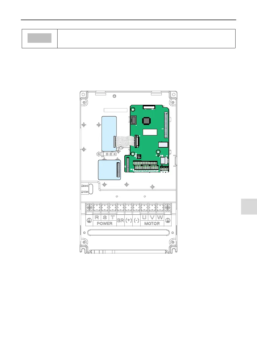
3.2.3 Control Board
If you need to connect the jumper, PG card or extension card, during control circuit wiring, remove the cover of
the AC drive rst (for removal steps, refer to Section 3.1.5). The location of control board, jumper and expan-
sion cards are shown in the following gure. (Refer to "Appendix A Expansion Optional Cards" to see how to
install optional cards.)
PG
card
(optional
)
Function
extension card
(optional)
Control
board
Figure 3-38 MD500 Control Board

 Loading...