3 Installation and Wiring
-
47
-
3
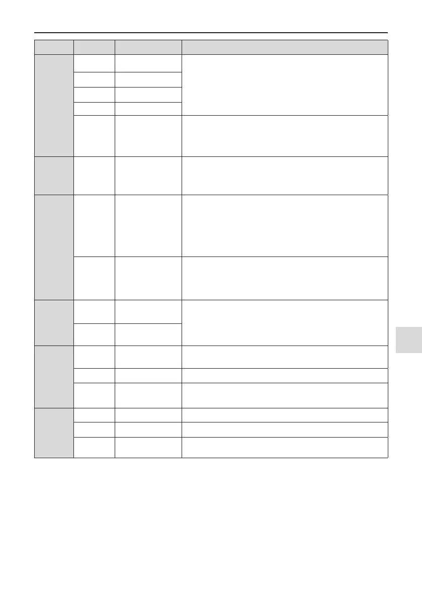
Type Terminal Name Description
Digital
inputs
DI1- OP Digital input 1
Optically-coupled isolation compatible with dual-polarity inputs
Input impedance: 1.39 kΩ
Voltage range for inputs: 9 to 30 V
DI2- OP Digital input 2
DI3- OP Digital input 3
DI4- OP Digital input 4
DI5- OP
High-speed pulse
input
In addition to having the same features as DI1 to DI4, DI5 can also
be used for high speed pulse inputs.
Max. input frequency: 100 kHz
Input impedance: 1.03 kΩ
Analog
outputs AO1-GND Analog output 1
Either a voltage or a current output, determined by jumper J7.
Output voltage range: 0 to 10 V
Output current range: 0 to 20mA
Digital
outputs
DO1-CME Digital output 1
Optically-coupled isolation, dual-polarity open-collector output
Output voltage range: 0 to 24V
Output current range: 0 to 50mA
Note that CME and COM are internally insulated, but are shorted
externally by a jumper. In this case, DO1 is driven by +24 V by
default. Remove the jumper link if you need to apply external power
to DO1.
FM- COM
High-speed pulse
output
Controlled by F5-00 (FM terminal output selection).
Max. output frequency: 100 kHz.
When used as an open-collector output, the specication is the same
as for DO1.
Relay
outputs
T/A-T/B
Normally-closed
(NC) terminal
Contact driving capacity:
250 VAC, 3 A, Cos Φ = 0.4
30 VDC, 1 A
T/A-T/C
Normally-open (NO)
terminal
Auxiliary
interfaces
J13
Extension card
interface
Interface for the 28-core terminal and optional cards (I/O extension
card, PLC card and various bus cards)
J4 PG card interface Open-collector, differential and Resolver are selectable options.
J11
External operating
panel interface
Connected to an external operating panel.
Jumpers
<3>
J7 AO1 output selection Either a voltage or a current output, voltage output by default
J9 AI2 input selection Either a voltage or a current iutput, voltage input by default
J10
AI2 input impedance
selection
Either 500 Ω or 250 Ω input, 500 Ω input by default
●
<1> When the ambient environment is above 23°C, the output current must be de-rated for 1.8 mA per 1°C
temperature rise. The maximum output current is 170 mA at 40°C. When OP is connected to 24 V, the cur-
rent of the DI must also be considered.
●
<2> Select 500 Ω or 250 Ω input impedance according to with-load capacity of signal source. For example,
if 500 Ω is selected, maximum output voltage of signal source must not be smaller than 10 V so that AI2
can measure 20 mA current.
●
<3> For positions of jumpers J7, J9 and J10, refer to Figure 3-39.

 Loading...