5 Basic Operations and Trial Run
-
67
-
5
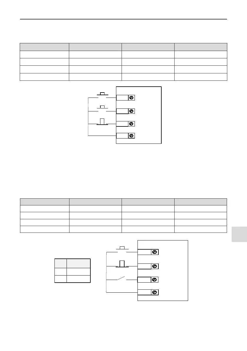
F4-11 = 2: Three-wire Control Mode 1. In this mode, DI3 is a three-wire control terminal. DI1 is set for forward
run function and DI2 is set for reverse run function.
The parameters are set as below:
Function Code Parameter Name Value Function Description
F4-11 Terminal I/O control mode 2 Three-wire control mode 1
F4-00 DI1 function selection 1 Forward RUN (FWD)
F4-01 DI2 function selection 2 Reverse RUN (REV)
F4-02 DI3 function selection 3 Three-wire control
DI1
FWD
Run enabled
DI3
COM
REV
DI2
SW1
SW3
SW2
Figure 5-7 Three-wire control mode 1
In this mode, on normal condition (SW3 closed), after you press down SW1, motor rotates in forward direction.
After you press down SW2, motor rotates in reverse direction. Motor stops immediately when SW3 opens. SW3
must remain closed during START sequence and during normal RUN operation. Signals from SW1 and SW2
are valid only with SW3 closed. The motor status is determined by the key that you last press down.
F4-11 = 3: Three-wire Control Mode 2. In this mode, DI3 is three-wire control terminal. DI1 determines whether
the RUN command is enabled and DI2 determines running direction.
The parameters are set as below:
Function Code Parameter Name Value Function Description
F4-11 Terminal I/O control mode 3 Three-wire control mode 2
F4-00 DI1 function selection 1 RUN enabled
F4-01 DI2 function selection 2 Reverse RUN
F4-02 DI3 function selection 3 Three-wire control
K
0
1
Running
direction
Forward
Reserve
DI1
Running command
Stop
DI3
COM
Running direction
DI2
SW2
SW
1
K
Figure 5-8 Three-wire control mode 2
In this mode, when SW1 is closed, after you press down SW2, motor rotates in forward direction with K open
and in reverse direction with K closed. Motor stops immediately when SW1 opens. SW1 must remain closed
during START sequence and during normal RUN operation. Signals from SW2 are valid only with SW1 closed.

 Loading...