6 Troubleshooting and Solutions
-
80
-
6
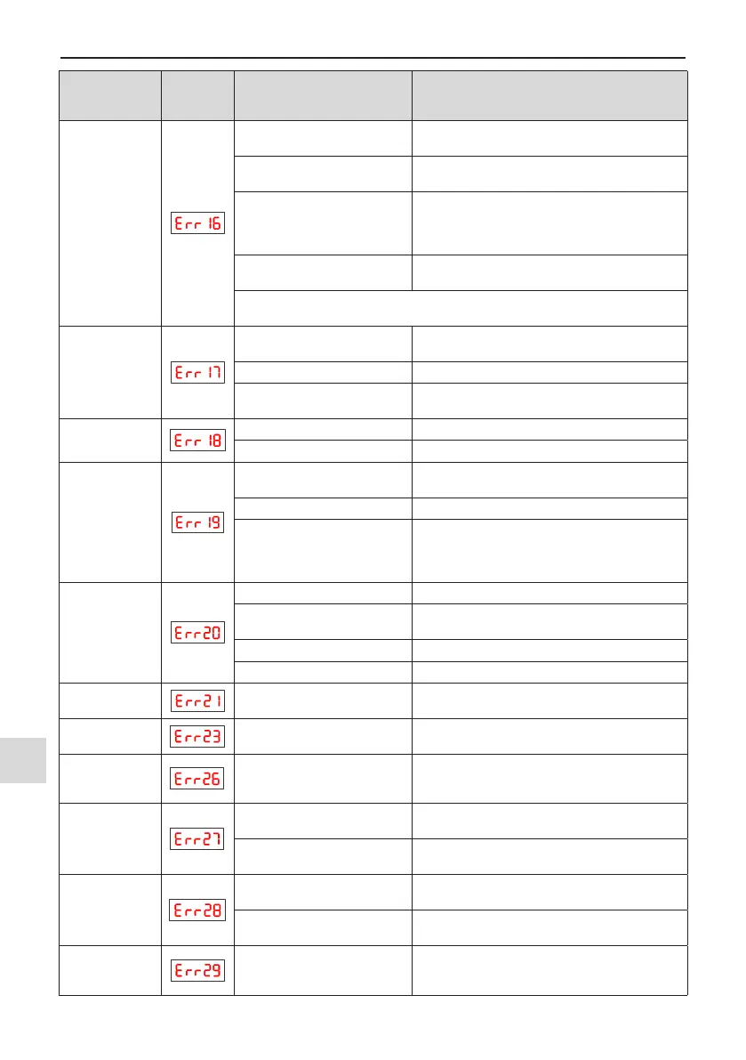
Fault Name
Operating
Panel
Display
Cause Possible Solution
Communication
fault
● Host computer is in abnormal
state.
● Check the cable of host computer.
● Communication cable is
abnormal.
● Check the communication cables.
● The serial port communication
protocol (F0-28) of extension
communication card is set
improperly.
● Set F0-28 of extension communication card
correctly.
● Communication parameters in
group Fd are set improperly.
● Set communication parameters in group Fd
properly.
● After all the preceding checkings are done but the fault still exists, restore the
default settings.
Contactor fault
● Drive board and power supply
are abnormal.
● Replace drive board or power supply board.
● Contactor is abnormal. ● Replace contactor.
● The lightning protection board
is abnormal.
● Replace the lightning protection board.
Current detection
fault
● The hall is abnormal. ● Replace the hall element.
● The drive board is abnormal. ● Replace the drive board.
Motor auto-tuning
fault
● Motor parameters are not set
according to nameplate.
● Set motor parameters correctly according to
nameplate.
● Motor auto-tuning times out. ● Check the cable connecting AC drive and motor.
● The encoder is abnormal.
● Check whether F1-27 (encoder pulses per
revolution) is set correctly. Check whether signal
lines of encoder are connected correctly and
securely.
Encoder fault
● Encoder is not matched. ● Set the type of encoder correctly.
● Encoder wiring is incorrect.
● Check the PG card power supply and phase
sequence.
● Encoder is damaged. ● Replace encoder.
● PG card is abnormal. ● Replace PG card.
EEPROM
read-write fault
● The EEPROM chip is
damaged.
● Replace the main control board.
Short circuit to
ground
● Motor is short circuited to the
ground.
● Replace cable or motor.
Accumulative
running time
reached
● Accumulative running time
reaches the setting value.
● Clear the record through parameter initialization.
User-dened
Fault 1
● User-dened fault 1 is input
via DI.
● Reset the operation.
● User-dened fault 1 is input
via virtual I/O.
● Reset the operation.
User-dened
Fault 2
● User-dened fault 2 is input
via DI.
● Reset the operation.
● User-dened fault 2 is input
via virtual I/O.
● Reset the operation.
Accumulative
power-on time
reached
● Accumulative power-on time
reaches the setting value.
● Clear the record through parameter initialization.

 Loading...