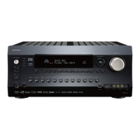
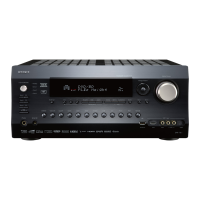
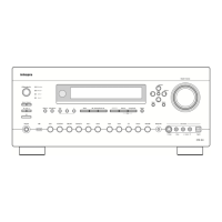
30
Connecting Antennas
This chapter explains how to connect the supplied indoor
FM antenna and AM loop antenna, and how to connect
commercially available outdoor FM and AM antennas.
The supplied indoor FM antenna is for indoor use ony.
If you cannot achieve good reception with the supplied
indoor FM antenna, try using a commercially available
outdoor FM antenna instead.
E
GND
“Net
-
Tune”
is
a
trademark
of
Onkyo
Corporation.
ETHERNET
(
Net
-
Tune
)
A
RS
232
IR
IN
+
12
V DC PWR SUPPLY
MAIN
GND
ZONE
3
ZONE
2
20mA MAX.
12 V
TRIGGER
OUT
E
MODEL NO.
DTR
-
10.5
GND
C
D
E
B
A
12
V
TRIGGER
OUT
100mA MAX.
100mA MAX.
100mA MAX.
TOTAL
100mA MAX.
200mA MAX.
UDD
AC
INLET
A
L
R
FRONT SURR SURR
BACK
CENTER
SUB
WOOFER
SUB
WOOFER
FRONT
L
CENTERFRONT
R
SURR BACK
L
(
ASSIGNABLE
)
SURR
R
SURR
L
FRONT
R
(
BTL
)
FRONT
L
(
BTL
)
PRE
OUT
A
(
SINGLE
)
PRE
OUT B
AC 120V 60Hz
SWITCHED
120W 1A MAX.
AC
OUTLET
SPEAKERS A
SPEAKERS B
22
1
66
55
44
33
22
11
OPTICAL COAXIAL
AUDIO IN
1
3
2
1
PH
2
3
9
8
7
6
5
4
4
5
RL
LR
LR
R L
G
IN
1
IN
2
HDMI
S
VIDEO VIDEO
IN IN
IN
1
IN
2
3
2
1
Y
P
B
P
R
COMPONENT
VIDEO
IN
3
6
5
4
Y
P
B
P
R
2
1
4
3
ANTENNA
FM
75
B
SURR BACK
R
(
ASSIGNABLE
)
DIGITAL IN DIGITAL IN
LR
S VIDEOS VIDEO VIDEOVIDEO
CD
OUT
OUT
F
L
OUT
IH
OUT OUT
J
K
OUT
1
AM
1
SBR SBL
SR SL
SUB C
FR FL
SBR SBL
SR SL
SUB C
FR
FL
MULTI
-
CH
IN
1
MULTI
-
CH
IN
2
B
OUT
Y
P
B
P
R
Y
P
B
P
R
COMPONENT VIDEO
IN
(
HD/BNC
)
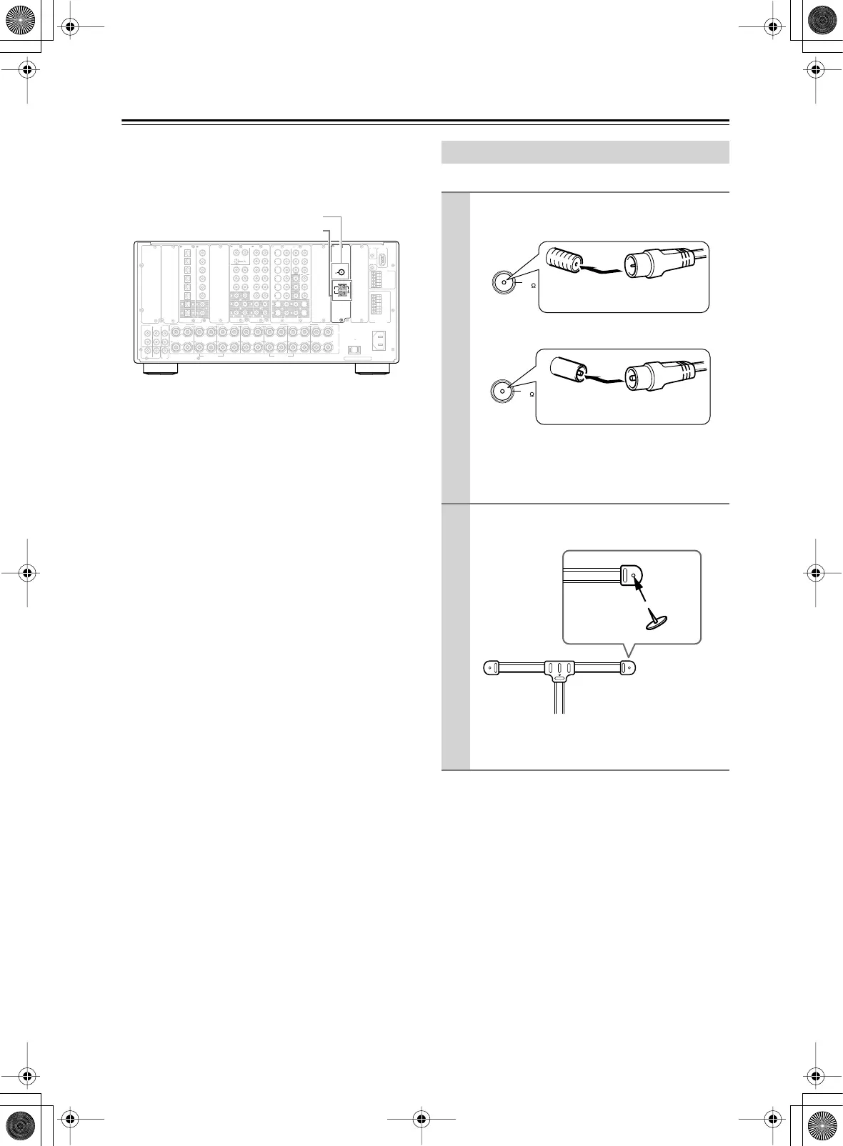
FM antenna connector
AM antenna push terminals
Connecting the Indoor FM Antenna
1
Attach the FM antenna, as shown.
■
USA and Canadian Models
■
Australian Model
Once your DTR-10.5 is ready for use, you’ll
need to tune into an FM radio station and adjust
the position of the FM antenna to achieve the best
possible reception.
2
Use thumbtacks or something similar to
fix the FM antenna into position.
Caution:
Be careful that you don’t injure
yourself when using thumbtacks.
FM
75
Insert the plug fully
into the socket.
FM
75
Insert the plug fully
into the socket
Thumbtacks, etc.