42
Connecting AV Components
—Continued
The i.LINK (AUDIO) terminal is available when the i.LINK terminal board [A] is installed.
What is i.LINK
i.LINK is an appellation of IEEE1394, which is the digital interface standard defined by the Institute of Electrical and
Electronics Engineers (IEEE).
Connecting i.LINK
(AUDIO)-supported devices allows high speed transfer of data such as digital sound between the
linked devices, and their control.
What is i.LINK (AUDIO)
The DTR-10.5 supports “i.LINK (AUDIO)” of the i.LINK transfer format. Accordingly, “i.LINK (AUDIO)” must also
be supported for other devices that you want to connect to the DTR-10.5. The DTR-10.5 does not support other i.LINK
transfer formats such as “MPEG-2 TS” used for BS digital broadcasts or “DV” used for DVD recorders, digital video,
etc. The DTR-10.5 connected to other i.LINK(AUDIO)-supported devices via i.LINK cable enables you to transfer
multichannel digital sound such as DVD-Audio and SACD (video signal is not supported).
Even when multiple devices are connected to each other, you can perform data transfer and control of target devices via
another device.
The IEEE interfaces on the DTR-10.5 are designed conforming to the standards below.
1. IEEE Std 1394a-2000, Standard for a High Performance Serial Bus
2. IEC60958 bitstream, DVD-Audio, and SACD in the AM824 Sequence adaptation layers of Audio and Music Data
Transmission Protocol 2.0
Copyright Protection System
The DTR-10.5 supports the DTCP (Digital Transmission Contents Protection) system. The DTCP system uses tech-
nologies for data encryption and authentication during the data transfer between the i.LINK-connected digital devices
in order to protect the copyright of the content against illegal duplication. To enjoy replaying DVD-Audio, etc., the
DTCP must also be supported by other devices connected to the DTR-10.5.
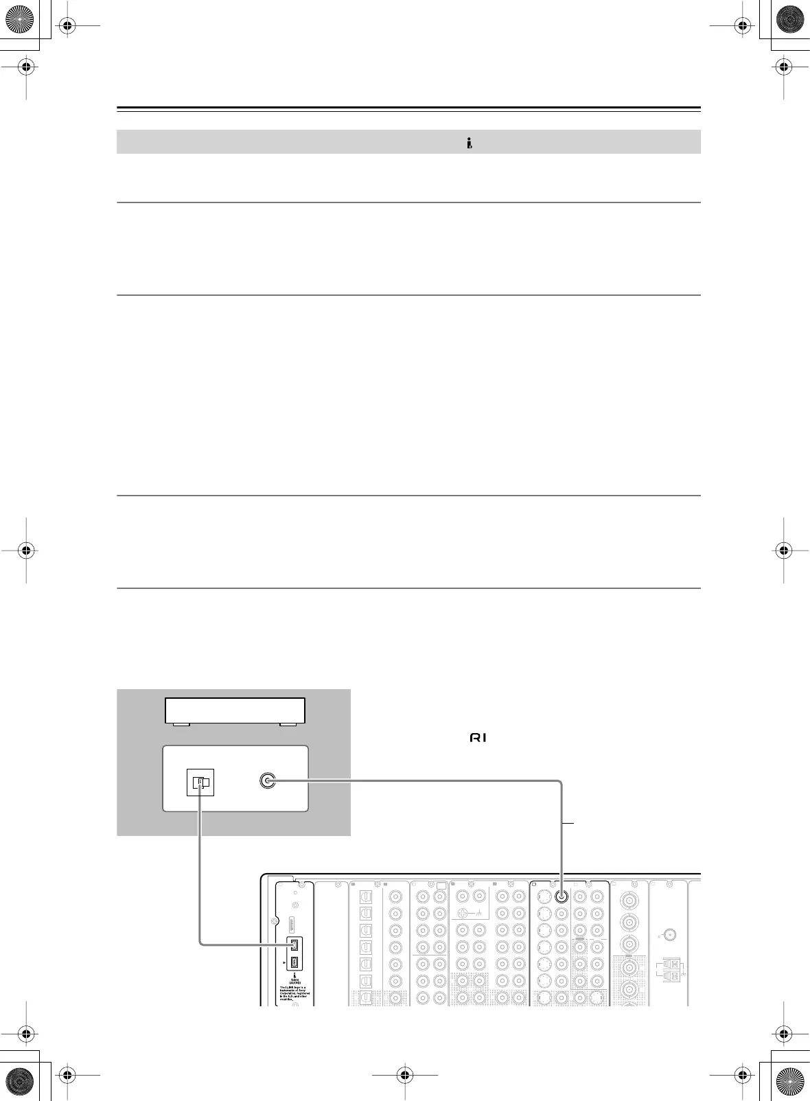
How to Make a Connection through the i.LINK (AUDIO) Interface
Use the S400 4-pin i.LINK cable to connect the i.LINK (AUDIO) terminal on the DTR-10.5 to the i.LINK (AUDIO)
terminal on the i.LINK (AUDIO)-enabled device.
• When using the i.LINK connection, you need to configure the audio input assignment settings in the “i.LINK” sec-
tion of the Audio Assign sub-menu (Some i.LINK-connected devices may require audio output settings).
• The DTR-10.5 supports only audio signal transmission through the i.LINK (AUDIO) interface. When connecting
video devices, you need to make a connection using other terminals for video signal.
Connection Using the i.LINK (AUDIO) Terminal ( )
E
GND
“Net
-
Tune”
is
a
trademark
of
Onkyo
Corporation.
ETHERNET
(
Net
-
Tune
)
A
1
66
55
44
33
22
11
OPTICAL COAXIAL
AUDIO IN
1
3
2
1
PH
2
9
8
7
6
5
4
4
RL
LR
G
S
VIDEO VIDEO
IN IN
IN
1
IN
2
3
2
1
Y
P
B
P
R
COMPONENT
VIDEO
IN
3
6
5
4
Y
P
B
P
R
13
ANTENNA
FM
75
DIGITAL IN DIGITAL IN
LR
CD
F
L
IH
J
K
OUT
1
AM
1
SR SL
SUB C
FR FL
SBR SBL
SR SL
SUB C
FR
FL
MULTI
-
CH
IN
1
B
OUT
Y
P
B
Y
P
B
P
R
COMPONENT VIDEO
IN
(
HD/ BNC
)
VIDEO OUT
In addition to the i.LINK
audio connection,
make sure to connect
the terminals for
images such as VIDEO
and/or S VIDEO
terminals.
Note:
If any other Integra product is connected to the DTR-10.5 via
i.LINK, system operation can be achieved via i.LINK cable. In that
case, disconnect the connection as it may introduce errors.