24
Speaker Placement
—Continued
The DTR-10.5 has two speaker terminal blocks for speaker system [A] and [B]. This allows you to build two 7.1 ch
home theater systems, and various speaker placements and connections are also available. For example, some channels
of either speaker system can be used for another room (Zone 2), or you can select one of two speaker systems for
playback according to the source.
When you use two speaker systems, you have to associate the speakers with the zone (e.g., Main A, Main B, etc.).
After making the association, for example, pressing the “MAIN A” button on the remote controller will output the
source from the speakers configured as “Main A.”
Here are some examples of speaker placement and zone association. These examples can be your reference when you
build your own home theater system. The illustration on the right represents the actual settings displayed corresponding to
each example. For details on configuring speaker placement and zone association, see page 88.
*In the following illustrations, white speakers denote speaker system [A] and gray ones denote speaker system [B].
*
Key to abbreviations:
FL
: Front left speaker;
FR
: Front right speaker;
C
: Center speaker;
SL
: Surround left speaker;
SR
: Surround right speaker;
SBL
: Surround back left speaker;
SBR
: Surround back right speaker;
SW
: Subwoofer
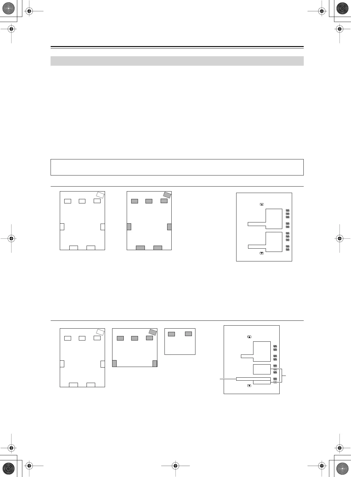
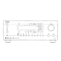
Main room A: 7.1 ch speaker system; Main room B: 7.1ch speaker system
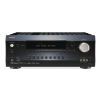
Main room A: 7.1 ch speaker system; Main room B: 5.1 ch speaker system; Sub room (Zone 2): 2 ch
speakers
Connection Examples
When you wish to configure 7.1 ch speaker system in the main room A only, the initial setting can be used without
any modification.
FL C
SBL SBR
SW
FR
SR
SL
FL C
SBL SBR
SW
FR
SR
SL
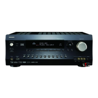
1-1.Speaker Config
=====================
Speaker A
a.Front L/R :Main A
b.Center :Main A
c.Surr L/R :Main A
d.Surr Back
:Main A 2ch
e.Subwoofer :Main A
Speaker B
f.Front L/R :Main B
g.Center :Main B
h.Surr L/R :Main B
i.Surr Back
:Main B 2ch
j.Subwoofer :Main B
• Set all the zone parameters for speaker system [A] to “Main A.”
• Set all the zone parameters for speaker system [B] to “Main B.”
• Pressing the [Main A] or [Main B] button causes the sound to be output from
the speaker system associated with the zone button. Both speaker systems
cannot be selected simultaneously.
*If you set all the zone parameters for speaker system [B] to “Main A” and play a single
source, the same audio signal will be output from both speaker systems [A] and [B].
Main room A Main room B
FL C
SBL SBR
SW
FR
SR
SL
FL C
SW
FR
FL
FR
SR
SL
1-1.Speaker Config
=====================
Speaker A
a.Front L/R :Main A
b.Center :Main A
c.Surr L/R :Main A
d.Surr Back
:Main A 2ch
e.Subwoofer :Main A
Speaker B
f.Front L/R :Main B
g.Center :Main B
h.Surr L/R :Main B
i.Surr Back
:Powered Zone 2
j.Subwoofer :Main B
• Set all the zone parameters for speaker system [A] to “Main A.” Set the zone parameters for
speaker system [B] to “Main B” and “Zone 2” accordingly.
• Both main room A and B cannot be used simultaneously. However, while either of the main
rooms is used, you can enjoy a different source in Zone 2.
• Note that when you use Zone 2, the surround back speakers for main room A cannot be used
since Zone 2 uses the surround back speaker circuit for main room A.
Main room A
Main room B
Zone 2
Main B
Powered
Zone 2