31
Connecting Antennas
—Continued
The supplied indoor AM loop antenna is for indoor use
only.
If you cannot achieve good reception with the supplied
indoor AM loop antenna, try using a commercially
available outdoor AM antenna.
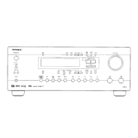
If you cannot achieve good reception with the supplied
indoor FM antenna, try using a commercially available
outdoor FM antenna instead.
Notes:
• Outdoor FM antennas work best outside, but acceptable
results can sometimes be obtained when installed in an attic
or loft.
• For best results, install the outdoor FM antenna well away
from tall buildings, preferably with a clear line of sight to
your local FM transmitter.
• Outdoor antennas should be located away from possible
noise sources, such as neon signs, busy roads, etc.
• For safety reasons, outdoor antennas should be situated well
away from power lines and other high voltage equipment.
• Outdoor antennas must be grounded in accordance with local
regulations to prevent electric shock hazards.
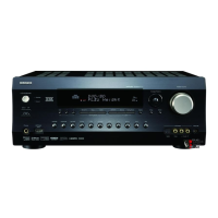
Using a TV/FM Antenna Splitter
It’s best not to use the same antenna for both FM and
TV reception, as this can cause interference problems.
If circumstances demand it, use a TV/FM antenna
splitter, as shown.
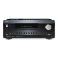
If good reception cannot be achieved using the supplied
AM loop antenna, an outdoor AM antenna can be used
in addition to the loop antenna, as shown.
Outdoor AM antennas work best when installed outside
horizontally, but good results can sometimes be obtained
indoors by mounting it horizontally above a window.
Note that the AM loop antenna should be left connected.
Outdoor antennas must be grounded in accordance with
local regulations to prevent electric shock hazards.
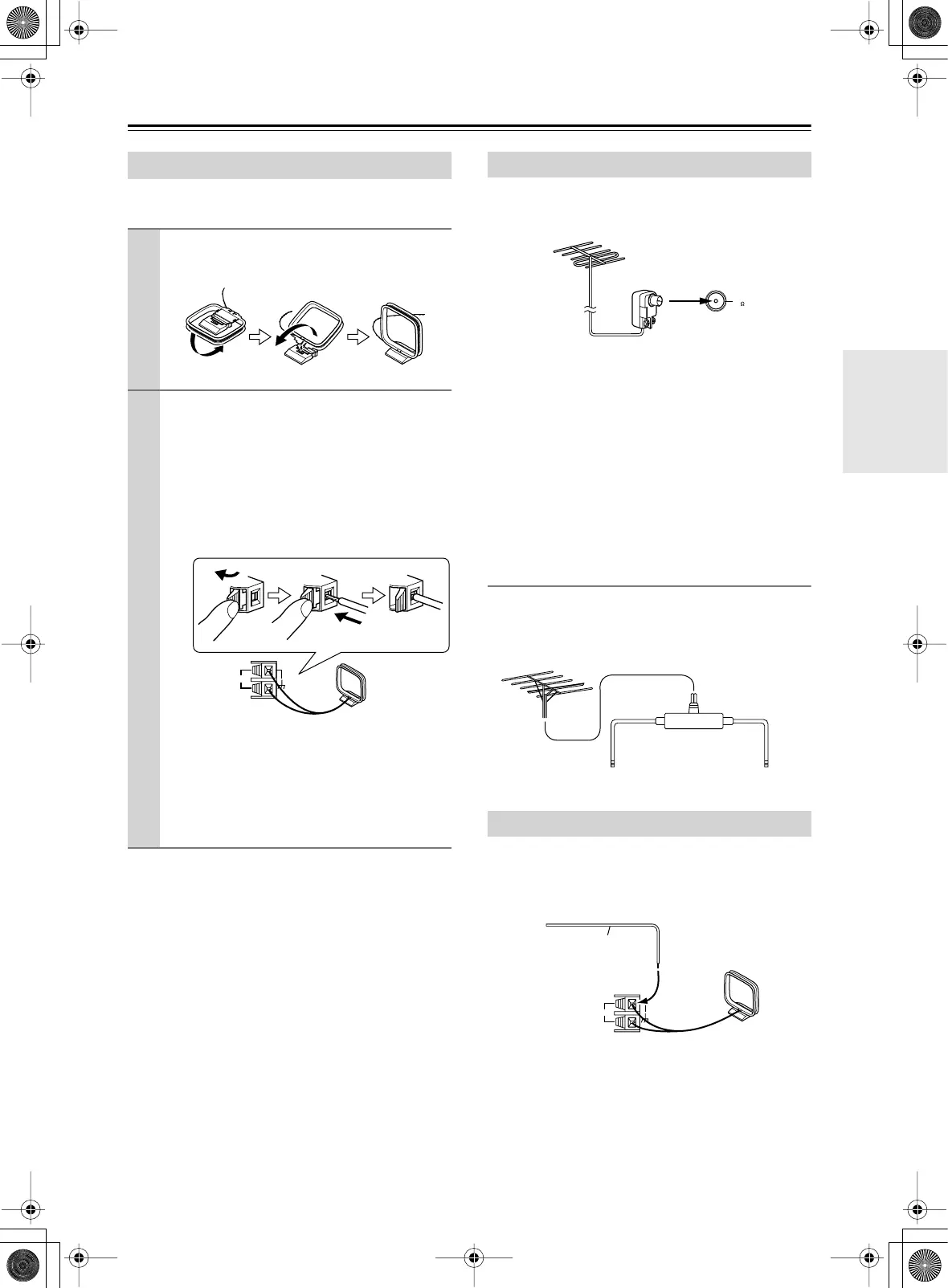
Connecting the AM Loop Antenna
1
Assemble the AM loop antenna, inserting
the tabs into the base, as shown.
2
Connect both wires of the AM loop
antenna to the AM push terminals, as
shown.
(The antenna’s wires are not polarity sensitive, so
they can be connected in either terminal)
Make sure that the wires are attached securely
and that the push terminals are gripping the bare
wires, not the insulation.
Once your DTR-10.5 is ready for use, you’ll
need to tune into an AM radio station and adjust
the position of the AM antenna to achieve the
best possible reception. Keep the antenna as far
away as possible from your DTR-10.5, TV,
speaker cables, and power cords.
AM
Push Insert wire Release
Connecting an Outdoor FM Antenna
Connecting an Outdoor AM Antenna
FM
75
To TV (or VCR)To AV receiver
TV/FM antenna splitter
AM
Outdoor antenna (aerial)
Insulated antenna cable
AM loop antenna
Installation and Connections