11
Before Using the DTR-10.5
—Continued
The option boards should be installed in their individual
designated slots. Installing the option board a different
slot may cause failure.
Installing the Option Boards
1
Turn off the power and unplug the power
cord both from the DTR-10.5 and electrical
outlet.
Be sure to turn off the power of the DTR-10.5.
Inserting or removing an option board with the
DTR-10.5 turned on may cause failure.
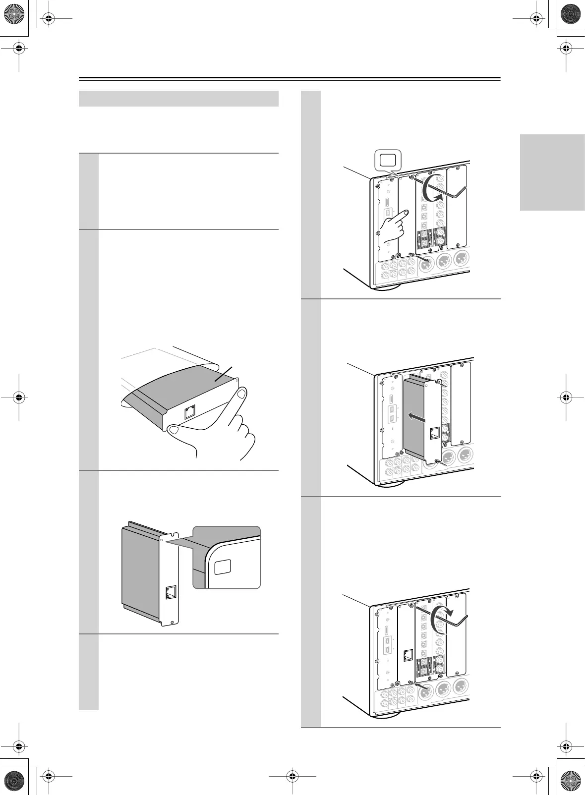
2
Take the option board out from the pack-
age carefully.
The option board incorporates many components,
terminals and connectors along with solderings
on its surface. Touching the board with your fin-
gers may cause failure or damage from static elec-
tricity, incorrect contact and so on. When
handling the board, be sure to hold the outer part
or panel section of the board without touching the
board surface.
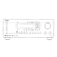
3
Check the alphabet letter on the option
board.
The alphabet letter is printed at the top left corner
of the panel section.
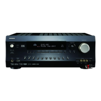
4
Remove the sub-panel with the same
alphabet letter as your option board from
the back of the DTR-10.5.
Use the supplied Allen wrench to loosen the screw
gradually, while holding the sub-panel so that the
panel will not drop down.
“Net
-
Tune
”
is
a
tradem
ark
of
Onkyo
Corporation.
ETHERNET
(
Net
-
Tune
)
B
Board
surface
“N
et
-
Tun
e”
is
a
tradem
ark
of
O
n
kyo
C
orpo
ration.
E
T
H
E
R
N
E
T
(
N
et
-
T
une
)
B
The sub-panels are fixed to the DTR-10.5 with
two screws at the top and bottom, while the panel
that covers slots [H] and [I] is fixed with four
screws at the top and bottom. Keep the removed
screws for fixing the option board.
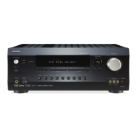
5
Insert the option board along the rail
softly. When the board comes to the posi-
tion where it stops but does not cover the
slot completely, push the board forward a
little bit more strongly.
6
Fix the option board firmly to the DTR-10.5
using the removed screws.
Be sure to tighten the screws firmly to the
DTR-10.5. If the screws are loose, contact failures
for ground or signal wires may occur at the section
between the DTR-10.5’s slot terminal and the
option board, which may cause the DTR-10.5 or
board to fail.
L
R
L
R
F
R
O
N
T
CENTER
S
U
R
R
S
U
R
R
B
A
C
K
S
U
B
W
O
O
F
E
R
S
U
R
R
B
A
C
K
R
S
U
R
R
R
S
U
B
W
O
O
F
E
R
(
A
S
S
IG
N
A
B
L
E
)
(
S
IN
G
L
E
)
(
A
S
S
IG
N
A
B
L
E
)
AUDIO
T
h
e
i.L
IN
K
lo
g
o
is
a
tr
a
d
e
m
a
r
k
s
o
f
S
o
n
y
C
o
r
p
o
r
a
tio
n
, r
e
g
i
s
t
e
r
e
d
in
th
e
U
.S
.
a
n
d
o
th
e
r
c
o
u
n
tr
ie
s
.
S
4
0
0
2
2
11
6
6
5
5
4
4
3
3
2
2
1
1
C
D
DIGITAL IN
DIGITAL IN
O
P
T
I
C
A
L
C
O
A
X
IA
L
O
U
T
E
A
B
P
R
E
O
U
T
A
B
L
R
L
R
F
R
O
N
T
CENTER
S
U
R
R
S
U
R
R
B
A
C
K
S
U
B
W
O
O
F
E
R
S
U
R
R
B
A
C
K
R
S
U
R
R
R
S
U
B
W
O
O
F
E
R
(
A
S
S
IG
N
A
B
L
E
)
(
S
IN
G
L
E
)
(
A
S
S
IG
N
A
B
L
E
)
AUDIO
T
h
e
i.L
IN
K
lo
g
o
is
a
tr
a
d
e
m
a
r
k
s
o
f
S
o
n
y
C
o
r
p
o
r
a
t
io
n
, r
e
g
i
s
t
e
r
e
d
in
t
h
e
U
.S
.
a
n
d
o
t
h
e
r
c
o
u
n
tr
i
e
s
.
S
4
0
0
2
2
11
6
6
5
5
4
4
3
3
2
2
1
1
C
D
DIGITAL IN
DIGITAL IN
O
P
T
IC
A
L
C
O
A
X
IA
L
O
U
T
E
A
P
R
E
O
U
T
A
“
N
e
t
-
T
u
n
e
”
is
a
tr
a
d
e
m
a
r
k
o
f
O
n
k
y
o
C
o
r
p
o
r
a
tio
n
.
ETHERNET
(
N
e
t
-
T
u
n
e
)
B
L
R
L
R
F
R
O
N
T
CENTER
S
U
R
R
S
U
R
R
B
A
C
K
S
U
B
W
O
O
F
E
R
S
U
R
R
B
A
C
K
R
S
U
R
R
R
S
U
B
W
O
O
F
E
R
(
A
S
S
IG
N
A
B
L
E
)
(
S
IN
G
L
E
)
(
A
S
S
IG
N
A
B
L
E
)
“
N
e
t
-
T
u
n
e
”
is
a
tr
a
d
e
m
a
r
k
o
f
O
n
k
y
o
C
o
rp
o
r
a
tio
n
.
ETHERNET
(
N
e
t
-
T
u
n
e
)
AUDIO
T
h
e
i.L
IN
K
lo
g
o
is
a
t
r
a
d
e
m
a
rk
s
o
f
S
o
n
y
C
o
r
p
o
r
a
t
io
n
, r
e
g
is
t
e
r
e
d
in
th
e
U
.S
.
a
n
d
o
t
h
e
r
c
o
u
n
t
r
ie
s
.
S
4
0
0
2
2
11
6
6
5
5
4
4
3
3
2
2
1
1
C
D
DIGITAL IN
DIGITAL IN
O
P
T
IC
A
L
C
O
A
X
IA
L
O
U
T
E
A
B
P
R
E
O
U
T
A
Getting Started