10
Before Using the DTR-10.5
—Continued
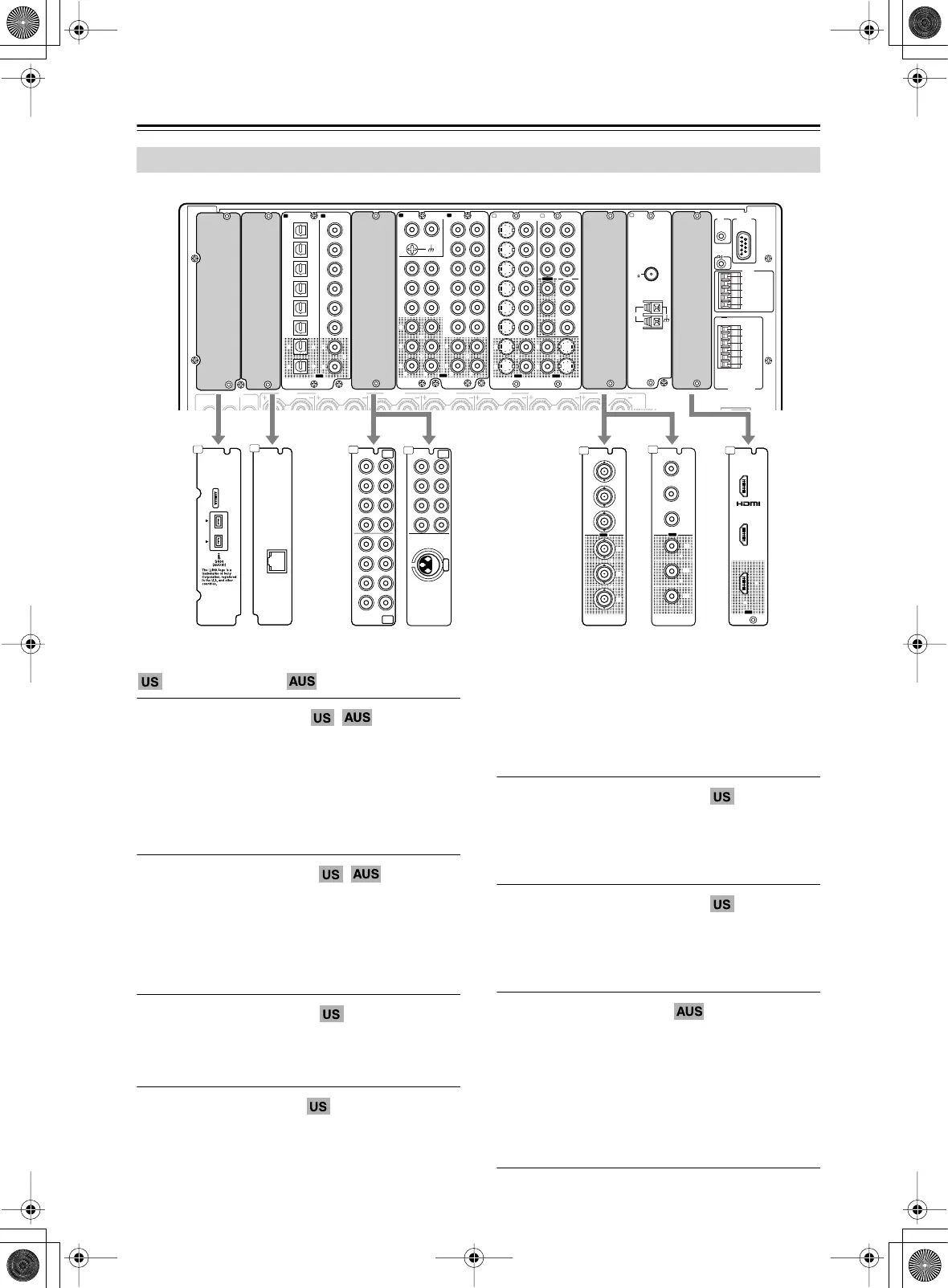
The following option boards are available for the DTR-10.5 as of October 2004.
Distributed regions (as of October 2004)
(the United States)
(Australia)
Product number: C-LINK
Provides i.LINK (AUDIO) terminals. Two input
terminals are available. This option board will be
inserted into slot A on the DTR-10.5.
These connectors are for connecting to an i.LINK
(AUDIO)-ready device using a 4-pin (S400) i.LINK
(AUDIO) cable. The DTR-10.5 complies with the
standards on audio only transimissions.
Product number: C-NET-A
Provides one Ethernet port for the Net-Audio connec-
tion. Connecting the network server to the port allows
you to enjoy music stored on your PC or delivered from
an Internet radio broadcast.
This option board will be inserted into slot B on the
DTR-10.5.
Product number: C-MULTI
Provides two analog multichannel input terminal sets.
This option board will be inserted into slot E on the
DTR-10.5.
Product number: C-AES
Provides one analog multichannel input terminal set and
one AES/EBU digital audio input jack.
The multichannel connector is for connecting compo-
nents with a multichannel output. The DIGITAL IN
(BALANCED) AES/EBU terminal is for connecting the
DVD player and other devices equipped with the XLR
(balanced) type digital audio output terminal.
This option board will be inserted into slot E on the
DTR-10.5.
Product number: C-CPNT-BNC
Provides BNC-type component video terminals. One input
terminal set and one output terminal set are available.
This option board will be inserted into slot J on the
DTR-10.5.
Product number: C-CPNT-RCA
Provides RCA-type component video terminals. One input
terminal set and one output terminal set are available.
This option board will be inserted into slot J on the
DTR-10.5.
Product number: C-HDMI
Provides HDMI terminals. Two input terminals and one
output terminal are available.
This option board will be inserted into slot L on the
DTR-10.5.
This interface can transfer digital audio and video sig-
nals simultaneously. The terminal can be connected to
the HDMI terminal on components such as DVD player,
set top box (B tuner), projector, and digital TV.
Types of the DTR-10.5 Option Boards
GND
RS
232
IR
IN
+
12
V DC PWR SUPPLY
MAIN
GND
ZONE
3
ZONE
2
20mA MAX.
12 V
TRIGGER
OUT
E
GND
C
D
E
B
A
12
V
TRIGGER
OUT
100mA MAX.
100mA MAX.
100mA MAX.
TOTAL
100mA MAX.
200mA MAX.
AC
INLET
FRONT SURR SURR
BACK
FRONT
L
CENTERFRONT
R
SURR BACK
L
(
ASSIGNABLE
)
SURR
R
SURR
L
PRE
OUT
A
(
SINGLE
)
22
1
66
55
44
33
22
11
OPTICAL COAXIAL
AUDIO IN
1
3
2
1
PH
2
3
9
8
7
6
5
4
4
5
RL
LR
LR
R L
G
S
VIDEO VIDEO
IN IN
IN
1
IN
2
3
2
1
Y
P
B
P
R
COMPONENT
VIDEO
IN
3
6
5
4
Y
P
B
P
R
2
1
4
3
ANTENNA
FM
75
SURR BACK
R
(
ASSIGNABLE
)
DIGITAL IN DIGITAL IN
LR
S VIDEOS VIDEO VIDEOVIDEO
CD
OUT
OUT
F
IH
OUT OUT
K
OUT
1
AM
1
IN
1
IN
2
HDMI
L
OUT
IN
1
IN
2
HDMI
OUT
L
C-HDMI
J
OUT
Y
P
B
P
R
Y
P
B
P
R
COMPONENT VIDEO
IN
(
HD/ BNC
)
OUT
Y
P
B
P
R
Y
P
B
P
R
COMPONENT VIDEO
IN
(
HD/ BNC
)
J
C-CPNT-BNC C-CPNT-RCA
Y
P
B
P
R
Y
P
B
P
R
COMPONENT VIDEO
IN
4
OUT
J
“Net
-
Tune”
is
a
trademark
of
Onkyo
Corporation.
ETHERNET
(
Net
-
Tune
)
B
C-NET-A
“Net
-
Tune”
is
a
trademark
of
Onkyo
Corporation.
ETHERNET
(
Net
-
Tune
)
B
E
SBR SBL
SR SL
SUB C
FR FL
SBR SBL
SR SL
SUB C
FR
FL
MULTI
-
CH
IN
1
MULTI
-
CH
IN
2
SBR SBL
SR SL
SUB C
FR FL
SBR SBL
SR SL
SUB C
FR
FL
MULTI
-
CH
IN
1
MULTI
-
CH
IN
2
E
C-MULTI C-AES
DIGITAL IN
(
BALANCED
)
AES/ EBU
DIGITAL IN
(
BALANCED
)
AES/ EBU
SBR SBL
SR SL
SUB C
FR
FL
MULTI
-
CH
IN
1
E
A
A
C-LINK