Omni-Path Switches
Intel
®
Omni-Path Fabric Switches
Installation Guide May 2016
58 Doc. No.: H76456Rev 3.0US
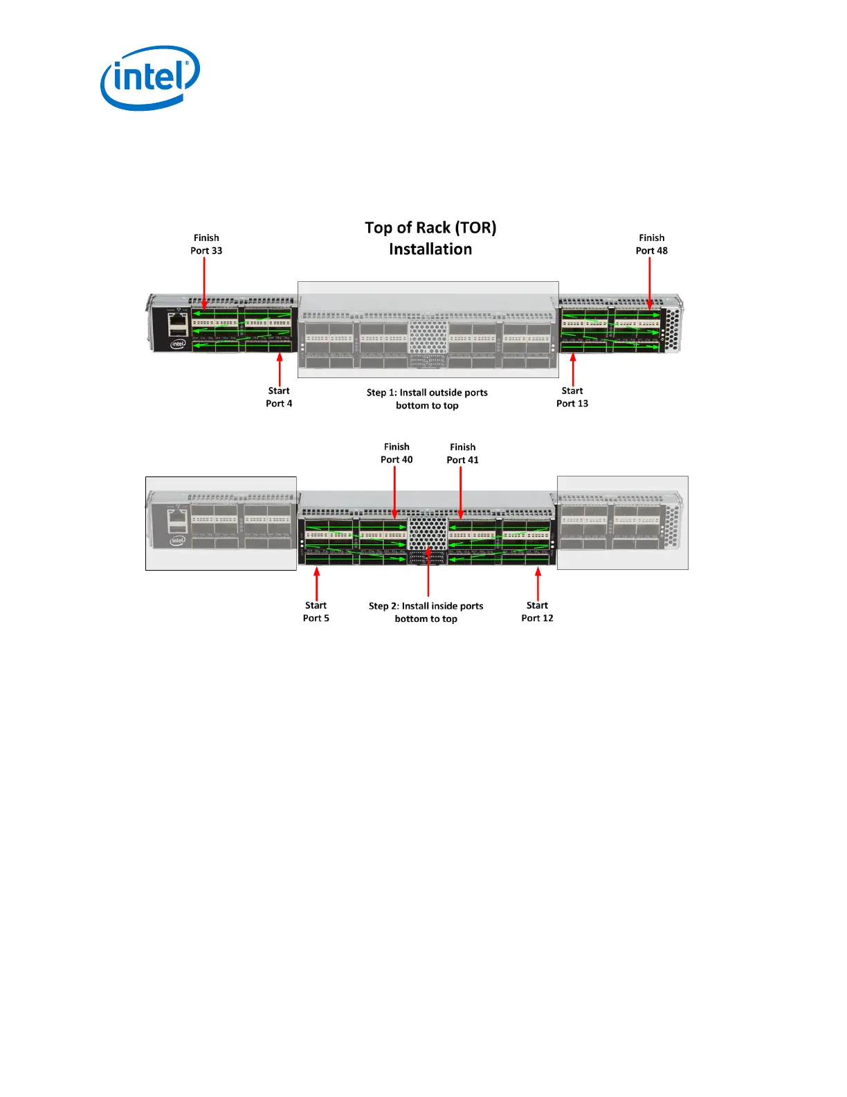
2.5.0.1 Edge Switch Cabling Recommendations
To minimize complexity, the following figure details cabling recommendations for the
48-port edge switch:
Figure 47. 48 Port Edge Switch Cabling Recommendations
2.5.0.2 Connecting Power
Note: For each power supply installed, a power cord must be installed in corresponding power
inlet.
1. Provide strain relief for the power cable(s).
2. If necessary, replace the closeout over the switch fan side.
3. Connect the power cables to a power distribution unit (PDU) or a proper AC power
outlet.
4. When the switch is plugged into an AC power outlet:
a. The system powers up.
b. The fans start.
c. The system performs a power-on self test.
Note: For the Director switches, make certain the DC ON/OFF switch is illuminated. If it is not,
press the button to supply power. The switch is located in the lower left corner on the
chassis spine side>
5. The switch, power supply(s), and fan LEDs light up.