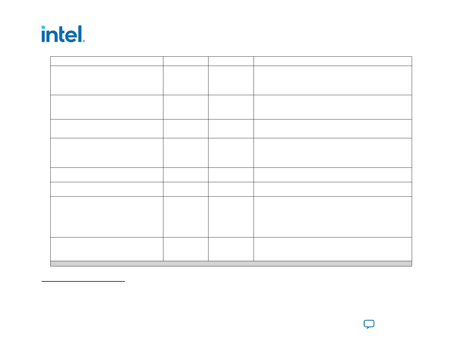
Pin Type Weak Pull-Up Function
pfl_flash_access_request
Output — For system-level synchronization. When necessary, this pin connects to a
processor or an arbiter. The PFL II IP core drives this pin high when the
JTAG interface accesses the flash or the PFL II IP configures the FPGA.
This output pin works in conjunction with the flash_noe and flash_nwe
pins.
flash_addr[]
Output — The flash memory address. The width of the address bus depends on the
density of the flash memory device and the width of the flash_data bus.
Intel recommends that you turn On the Set flash bus pins to tri-state
when not in use option in the PFL II .
flash_data[]
Input or Output
(bidirectional pin)
— Bidirectional data bus to transmit or receive 8-, 16-, or 32-bit data. Intel
recommends that you turn On the Set flash bus pins to tri-state when
not in use option in the PFL II.
(11)
flash_nce[]
Output —
Connects to the nCE pin of the flash memory device. A low signal enables
the flash memory device. Use this bus for multiple flash memory device
support. The flash_nce pin connects to each nCE pin of all the
connected flash memory devices. The width of this port depends on the
number of flash memory devices in the chain.
flash_nwe
Output —
Connects to the nWE pin of the flash memory device. When low enables
write operations to the flash memory device.
flash_noe
Output —
Connects to the nOE pin of the flash memory device. When low enables
the outputs of the flash memory device during a read operation.
flash_clk
Output —
For burst mode. Connects to the CLK input pin of the flash memory
device. The active edges of CLK increment the flash memory device
internal address counter. The flash_clk frequency is half of the
pfl_clk frequency in burst mode for a single CFI flash. In dual CFI flash
solution, the flash_clk frequency runs at a quarter of the pfl_clk
frequency. Use this pin for burst mode only. Do not connect these pins
from the flash memory device to the host if you are not using burst mode.
flash_nadv
Output — For burst mode. Connects to the address valid input pin of the flash
memory device. Use this signal to latch the start address. Use this pin for
burst mode only. Do not connect these pins from the flash memory device
to the host if you are not using burst mode.
continued...
(11)
Intel recommends that you do not insert logic between the PFL II pins and the host I/O pins, especially on the flash_data and
fpga_nconfig pins.
3. Intel Agilex Configuration Schemes
683673 | 2021.10.29
Intel
®
Agilex
™
Configuration User Guide
Send Feedback
82
 Loading...


