120 Intel Server Board SE7501BR2 Product Guide
Front Panel Header
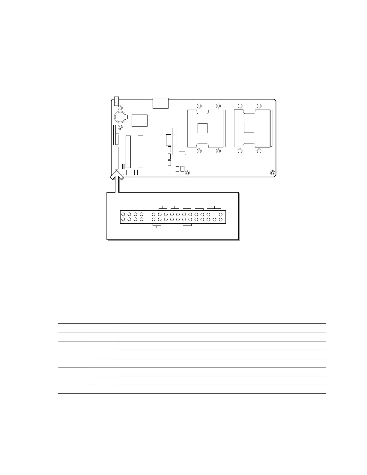
The front panel header provides connection to the front panel for power switching and LED
operation.
OM14668
33
34
F
G
1
2
A
B
C
D
E
A. Sleep Switch
B. Reset Switch
C. Power Switch
D. HDD LED
E. Power LED
F. NIC 2 LED
G. NIC 1 LED
Figure 33. Front Panel Header Connection Location
Table 34. Front Panel Header Connection Descriptions
Location Pins Description
A 19 & 21 Pressing the sleep button immediately puts the server board into the sleep mode
B 15 & 17 Pressing the reset button restarts the boot process
C 11 & 13 Pressing the power switch removes all by standby power from the board
D 7 & 9 LED show hard disk drive activity
E 1 & 5 LED shows power on
F 22 & 24 LED shows network interface controller activity
G 12 & 14 LED shows network interface controller activity

 Loading...


