Description 19
NIC Connector and Status LEDs
The Intel
®
Server Board SE7501BR2 supports two RJ45 connectors, one for the 10/100-Megabit
Fast Ethernet controller (NIC1), and the other for the Gigabit Ethernet controller (NIC2).
NIC1 drives two LEDs on its RJ45 connector. These LEDs indicate link/activity on the LAN and
the speed of operation. This connector is on the right side when looking at the I/O area at the back
of the board. The green LED to the right of the connector indicates a network connection is in
place when it is on and transmit/receive activity when it is blinking. The green LED to the left of
the connector indicates 10 Mbps operation when it is off and100 Mbps operation when it is lit and.
See the following table for an overview.
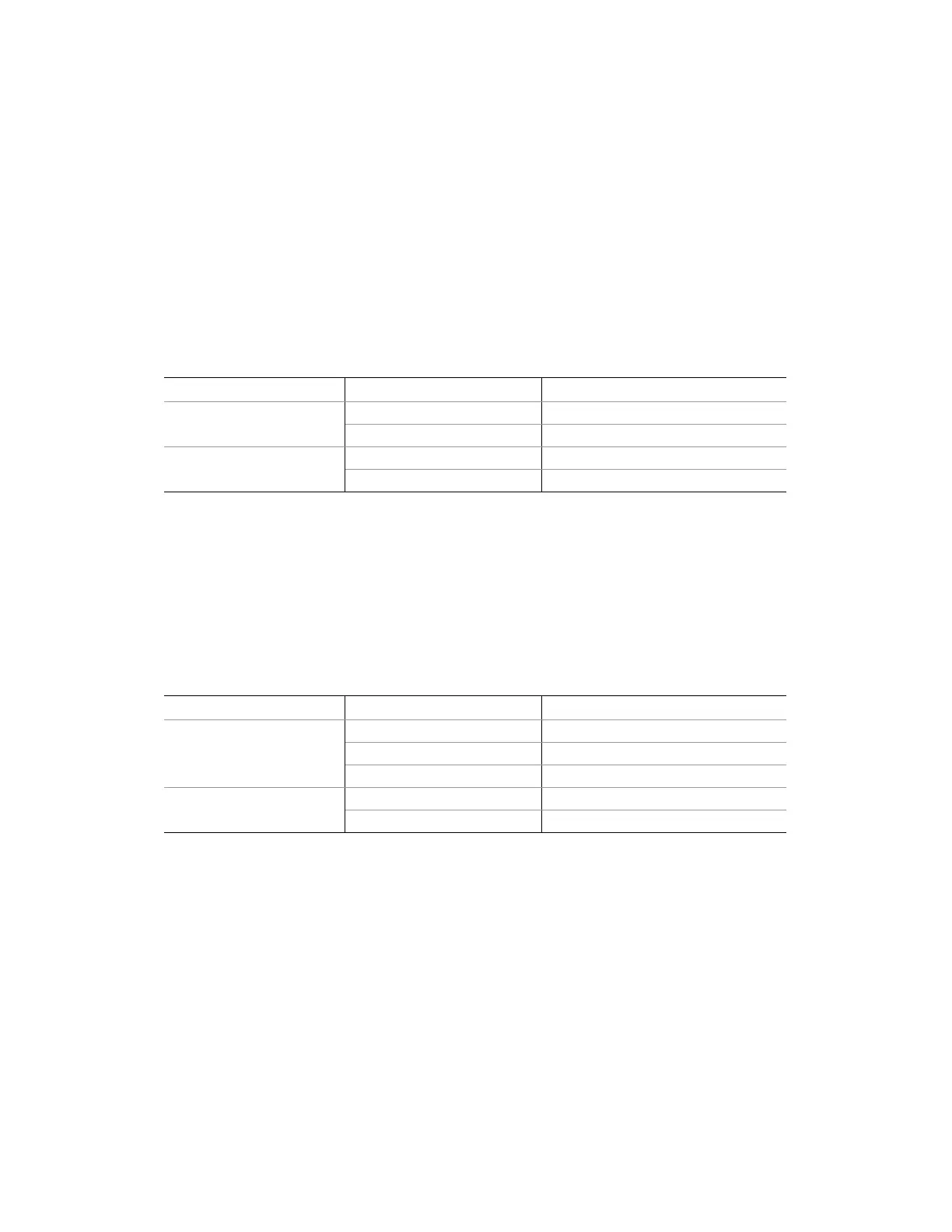
Table 3. 10/100 Megabit LEDs (NIC1)
LED Color LED State NIC1 State
Off 10-Mbps
Green (left)
On 100-Mbps
On On
Green (right)
Blinking Transmit / Receive activity
NIC2 drives two LEDs located on its RJ45 connector; this connector is on left side when looking at
the I/O area in the back of the board. The green LED to the right of the connector indicates a
network connection is in place when it is on, and transmit/receive activity when it is blinking. The
bi-color LED to the left of the connector indicates 10-Mbps when it is off, 100-Mbps operation
when it is green, and 1000-Mbps operation when it is yellow. See the following table for an
overview.
Table 4. Gigabit LEDs (NIC2)
LED Color LED State NIC2 State
Off 10-Mbps
Green 100-Mbps
Green/Yellow (left)
Yellow 1000-Mbps
On On
Green (right)
Blinking Transmit / Receive activity

 Loading...


