Description 11
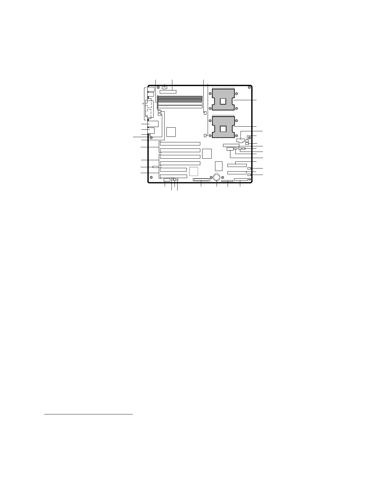
Server Board Connector and Component Locations
OM15026
A
B
C
E
F
G
H
P
Q
S
R
T
U
V
W
Y
Z
AA
CC
EE
GG
HH
II
JJ
KK
D
I
J
K
L
M
N
O
X
BB
FF
DD
A Primary Processor (CPU1) N System Fan 3 AA System Fan 1
B Secondary Processor (CPU2) O Front Panel Connector BB System Fan 2
C CPU Power P Jumper Block CC ID LED
D System Fan 6 Q Battery DD NIC 1 (10/100)
E System Fan 5 R LVD SCSI Connector EE NIC 2 (1 gigabit)
F Floppy Disk Drive Connector S HDD LED Connector FF System I/O Connectors
G IPMB Connector T Chassis Intrusion GG DIMM Sockets
H HSBP B U EMP in Use HH Aux Power
I HSBP A V Serial B II Main Power
J USB Connector W 32/33 PCI, Slots 5 & 6 JJ CPU1 Fan Connector
K Primary IDE (ATA 100) X ICMB KK CPU2 Fan Connector
L System Fan 4 Y 64/100 PCI-X, Slots 3 & 4
2
M Secondary IDE (ATA 100) Z 64/100 PCI-X, Slots 1 & 2
Figure 1. Server Board Connector and Component Locations
2
M-ROMB support provided via Slot4

 Loading...


