110 sur 140
Version 2.5 (11/2020) UL
Traduction de la notice d’utilisation originale
Mise en service et fonctionnement
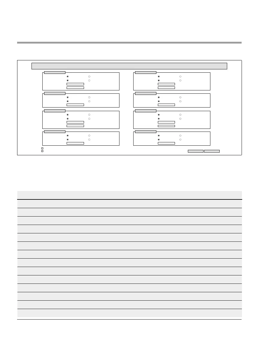
Digital I/O Settings
Digital I/O Settings
Submit Reset
Sensor 1
Type :
Polarity :
ON Delay [ms] :
OFF Delay [ms] :
PNP
positive
NPN
negative
0
0
I/O 1
Type :
Polarity :
Function :
PNP
positive
NPN
negative
PLC Input
Sensor 2
Type :
Polarity :
ON Delay [ms] :
OFF Delay [ms] :
PNP
positive
NPN
negative
0
0
I/O 2
Type :
Polarity :
Function :
PNP
positive
NPN
negative
PLC Input
I/O State LEDs enabled
Shutdown Aux Output
Sensor 3
Type :
Polarity :
ON Delay [ms] :
OFF Delay [ms] :
PNP
positive
NPN
negative
0
0
I/O 3
Type :
Polarity :
Function :
PNP
positive
NPN
negative
PLC Input
Sensor 4
Type :
Polarity :
ON Delay [ms] :
OFF Delay [ms] :
PNP
positive
NPN
negative
0
0
I/O 4
Type :
Polarity :
Function :
PNP
positive
NPN
negative
PLC Input
Les capteurs 1 à 4 sont toujours aectés aux capteurs de zone.
Des E/S supplémentaires peuvent être connectées à l’aide d’un câble en Y disponible en option.
Les E/S 1 à E/S 4 peuvent être congurées comme entrées ou sorties avec les fonctions suivantes:
Fonction Description
Aucune -
API Input Signal d'entrée de la API
API Output Signal de sortie vers la API
Sensor 5 Capteur de démarrage Zone 1 (la polarité doit être négative)
Sensor 6 Réserve
Sensor 7 Réserve
Sensor 8 Réserve
Control Input 1 Arrête la Zone 1
Control Input 2 Arrête la Zone 2
Control Input 3 Arrête la Zone 3
Control Input 4 Arrête la Zone 4
Control Input 5 - 8 Aucune fonction
Control Output 1 Zone 1 occupée
Control Output 2 Zone 2 occupée