Version 2.5 (11/2020) UL
Translation of the original operating manual 29 of 140
Assembly and installation
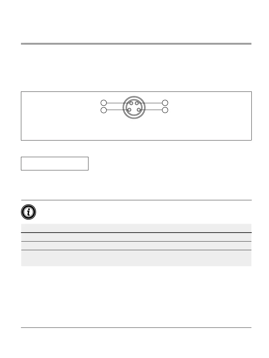
Connecting the sensors
Four sensors and four additional inputs or outputs (AUX I/O) can be connected at connections “Sensor 1, I/O 1” to
“Sensor 4, I/O 4”. PNP or NPN sensors as well as sensors with N/C or N/O contact can be used. The sensor type and
the function of the additional I/Os can be parametrised (see „Digital I/O - Settings“ on page 42). A Y-cable can be
used to connect a sensor and an input/output at the same connection (see „Accessories“ on page 66).
2
1
3
4
1 +24 V 3 Earth
2 AUX I/O 4 Sensor input
¾ Seal any unused connections with an M8 blind cap to achieve protection rate IP54.
NOTE
Connections are not short circuit-proof
In the event of a short circuit, particularly between Pin 1 and Pin 3, the internal fuse (PTC) in the MultiControl trips.
Standard operation can be resumed once the internal fuse has cooled down.
¾ Ensure the correct polarity.
The inputs and outputs are not galvanically separated.
Characteristic values for the inputs
Input voltage 0 V to 24 V DC
Input resistance ≥ 15 kΩ
Switching thresholds ≥ 15 V "High"
≤ 5 V "Low"