42 of 140
Version 2.5 (11/2020) UL
Translation of the original operating manual
Start-up and operation
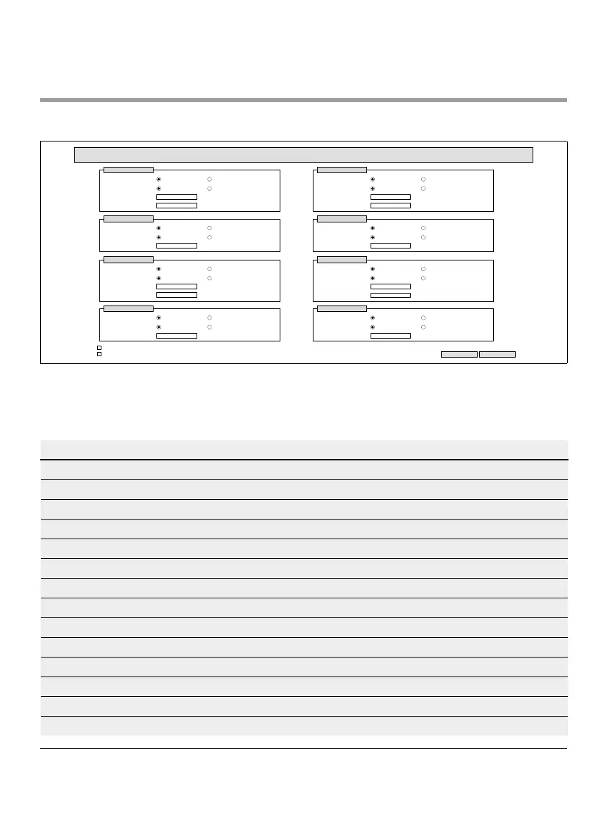
Digital I/O Settings
Digital I/O Settings
Submit Reset
Sensor 1
Type :
Polarity :
ON Delay [ms] :
OFF Delay [ms] :
PNP
positive
NPN
negative
0
0
I/O 1
Type :
Polarity :
Function :
PNP
positive
NPN
negative
PLC Input
Sensor 2
Type :
Polarity :
ON Delay [ms] :
OFF Delay [ms] :
PNP
positive
NPN
negative
0
0
I/O 2
Type :
Polarity :
Function :
PNP
positive
NPN
negative
PLC Input
I/O State LEDs enabled
Shutdown Aux Output
Sensor 3
Type :
Polarity :
ON Delay [ms] :
OFF Delay [ms] :
PNP
positive
NPN
negative
0
0
I/O 3
Type :
Polarity :
Function :
PNP
positive
NPN
negative
PLC Input
Sensor 4
Type :
Polarity :
ON Delay [ms] :
OFF Delay [ms] :
PNP
positive
NPN
negative
0
0
I/O 4
Type :
Polarity :
Function :
PNP
positive
NPN
negative
PLC Input
Sensors 1–4 are assigned to the zone sensors.
Additional I/Os can be connected by using an optional Y-cable.
I/O 1 to I/O 4 can be congured as inputs or outputs with the following functions:
Function Description
None -
PLC input Input signal from the PLC
PLC output Output signal to the PLC
Sensor 5 Start sensor zone 1 (polarity must be negative)
Sensor 6 Spare
Sensor 7 Spare
Sensor 8 Spare
Control input 1 Stops zone 1
Control input 2 Stops zone 2
Control input 3 Stops zone 3
Control input 4 Stops zone 4
Control input 5–8 No function
Control output 1 Zone 1 occupied
Control output 2 Zone 2 occupied