26 of 140
Version 2.5 (11/2020) UL
Translation of the original operating manual
Assembly and installation
5.4 Electrical installation
Connecting the power supply
Two type 3G3G-FL ribbon cables with a wire cross-section of 2x 2.5 mm
2
are used for the power supplies.
By using two ribbon cables, the RollerDrives and the sensors/logic have a separate voltage supply. This enables the
RollerDrives to be safely shut down without interrupting bus communication.
A ribbon cable distributor can be used to enable the MultiControl to be used as a replacement part in
existing systems (see „Accessories“ on page 66).
Both earth potentials (L-) of the power supplies are connected to one another in the MultiControl.
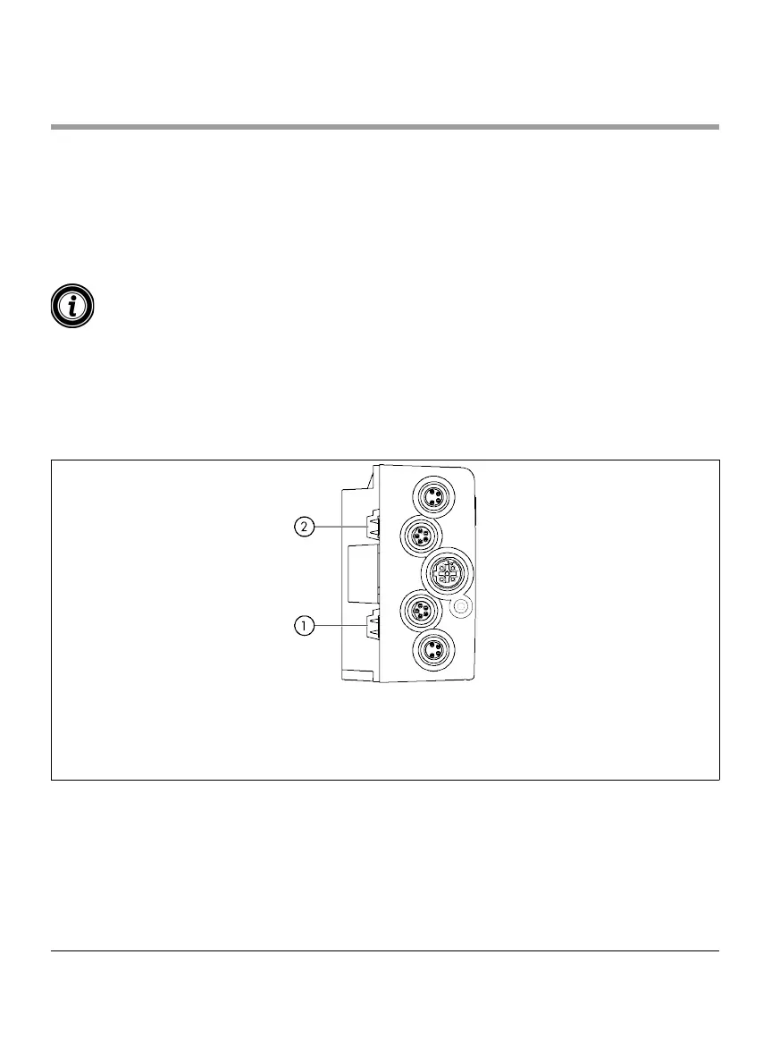
¾ Insert the ribbon cables with the correct orientation, without mechanical tension or torsion, into the cable
guides on the base plate. The cable guides have a form-t design (see gure). This means that the ribbon
cables can only be inserted with the correct orientation and the polarity of the cables cannot be reversed.
¾ If necessary, implement appropriate strain relief and vibration reduction measures.
1 Cable guide for power supply to logic and
sensors (L1)
2 Cable guide for power supply to RollerDrive (L2)
Upper pin: L+, brown cable wire Upper pin: L+, brown cable wire
Lower pin: L-, blue cable wire Lower pin: L-, blue cable wire
¾ Seal the ends of the ribbon cables with end caps to achieve protection rate IP54.
¾ Mount the MultiControl on the base frame to establish contact (see „Initial assembly“ on page 22).
¾ Connect the cables to the power source. Connect the brown wire to L+ and the blue wire to L-.