28 of 140
Version 2.5 (11/2020) UL
Translation of the original operating manual
Assembly and installation
Connecting the bus
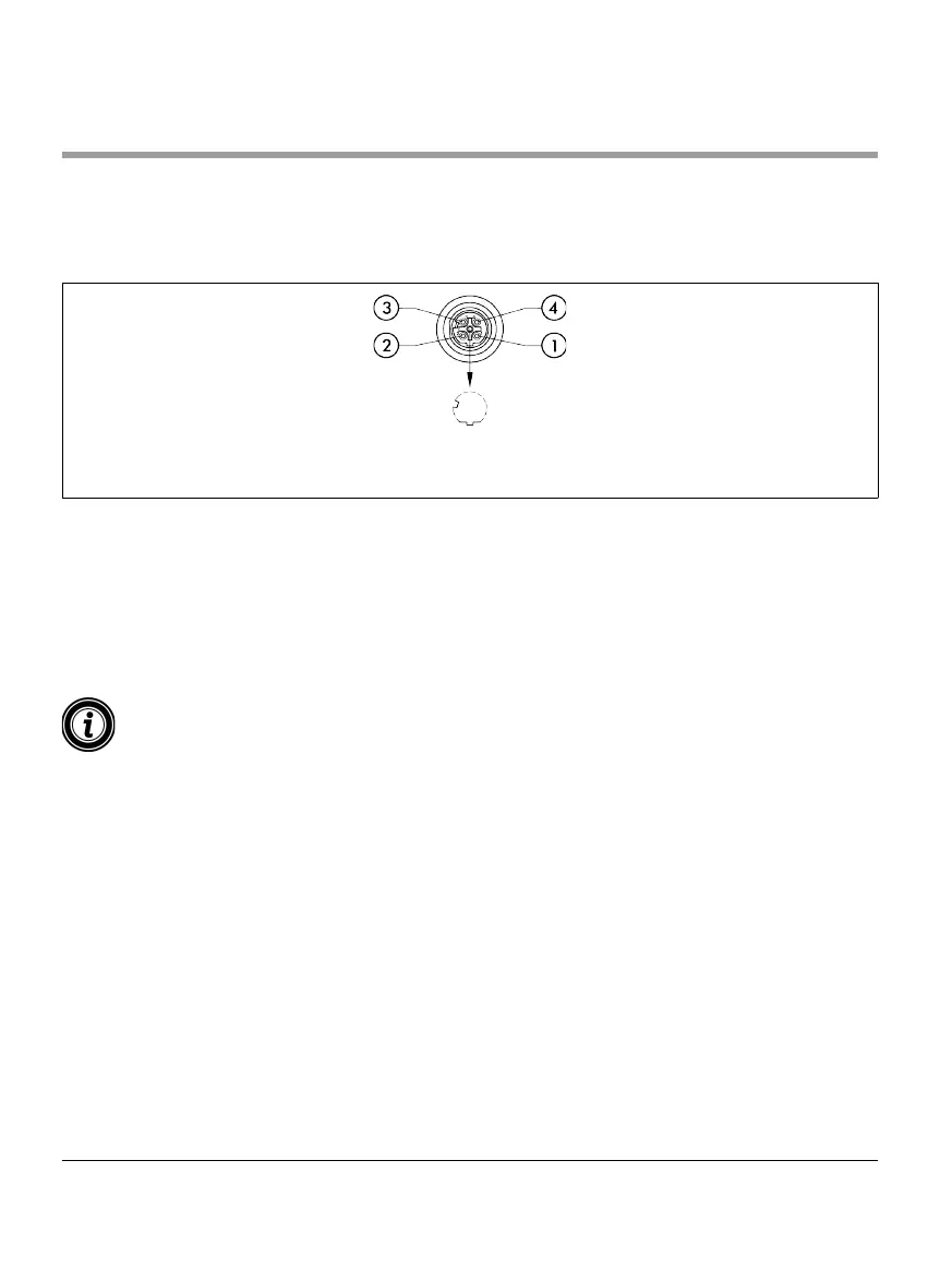
Connections “Link A” and “Link B” are suitable for M12 connectors, four-pin, D-coded, contact assignment as per IEC
61076-2-101.
1 Transmission Data TD+ 3 Transmission Data TD-
2 Receive Data RD+ 4 Receive Data RD-
The MultiControl features an integrated two-port switch. This enables the MultiControl to be integrated into line
structures of the bus wiring, for example.
¾ Observe the installation guidelines for the corresponding bus systems:
• PROFINET: PROFIBUS & PROFINET International (PI), www.probus.com
• EtherCAT: EtherCAT Technology Group, www.ethercat.org
• EtherNET/IP: ODVA, www.odva.org
¾ Seal any unused connections with an M12 blind cap to achieve protection rate IP54.
It is possible to connect the shielding of the bus cables on both sides of the MultiControl. This minimises EMC
problems.