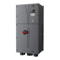
Goodrive350 IP55 High-ingress Protection Series VFD Function parameter list
-145-
10: HDIB
11: EtherCAT/PROFITNET/Ethernet IP
communication
12: PLC programmable card
13: Reserved
Set voltage
value via keypad
When the channel for voltage setup is set to
"keypad", the value of this function code is
digital voltage set value.
Setting range: 0.0%–100.0%
Voltage
acceleration
time
Voltage increase time means the time needed
from outputting the min. voltage to accelerating
to output the max. voltage.
Voltage decrease time means the time needed
from outputting max. voltage to outputting the
min. voltage
Setting range: 0.0–3600.0s
Voltage
deceleration
time
Set the upper/lower limit value of output voltage.
Vmax
Vmin
V set
Time t
t1 t2
t1=P04.29
t2=P04.30
Setting range of P04.31: P04.32–100.0% (rated
motor voltage)
Setting range of P04.32: 0.0%–P04.31
Flux-weakening
coefficient of
constant-power
zone
VF pull-in
current 1 of
synchronous
motor
When the synchronous motor VF control mode
is enabled, this parameter is used to set the
reactive current of the motor when the output
frequency is lower than the frequency set in
P04.36.
Setting range: -100.0%–+100.0% (of the motor
rated current)
VF pull-in
current 2 of
synchronous
motor
When the synchronous motor VF control mode
is enabled, this parameter is used to set the
reactive current of the motor when the output
frequency is higher than the frequency set in
P04.36.
Setting range: -100.0%–+100.0% (of the motor
rated current)

 Loading...