50
SERVICE MANUAL FOR SGR19 & SGR17
Fig. 3-105
• Sub-assemble the pump cam and the thrust plate
in advance, paying attention to thrust plate di-
rection.
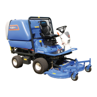
Fig. 3-106
• Insert the starting spring pin into the cylinder
block and install the starting spring.
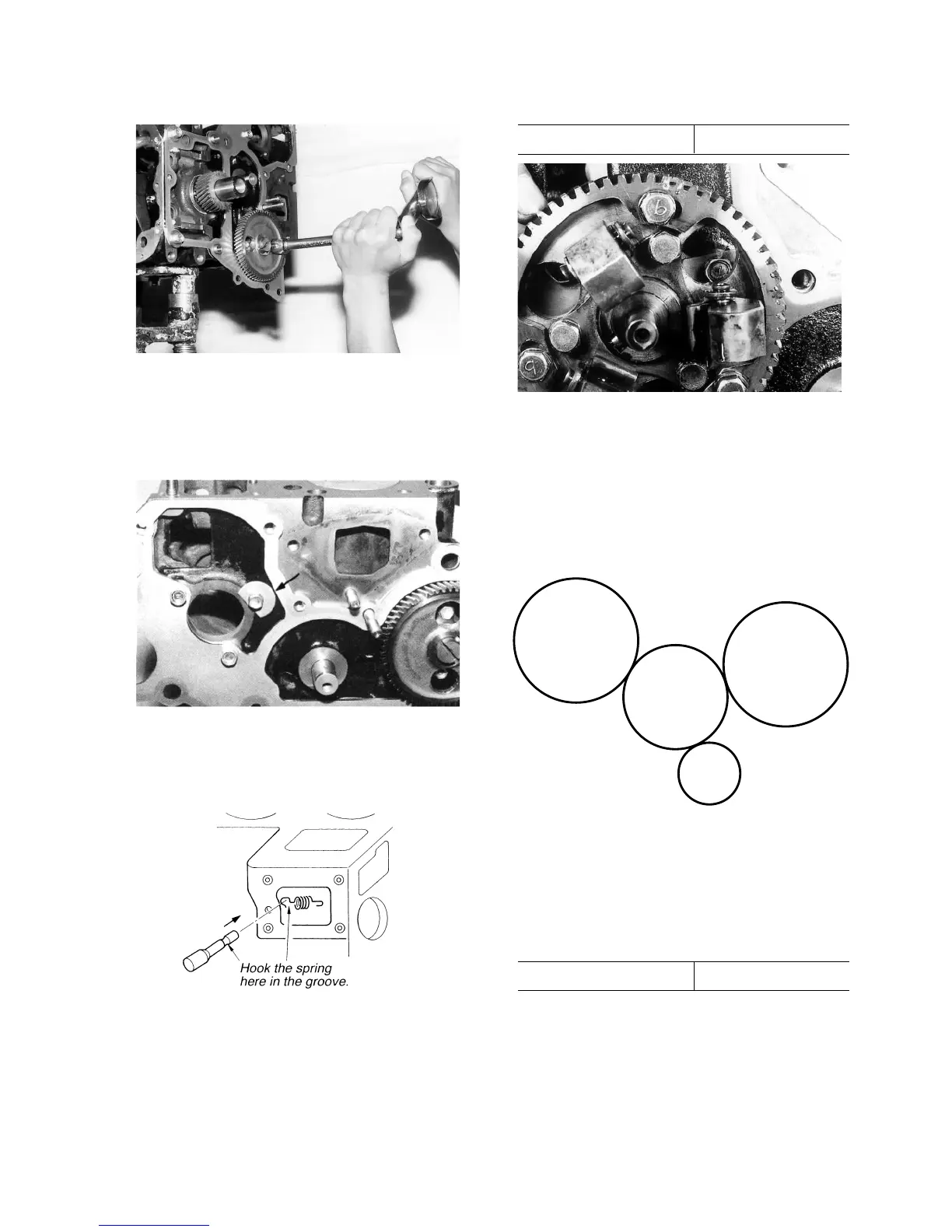
Fig. 3-107
• Install the injection cam gear assembly.
• Retain the injection pump cam shaft with the
thrust plate and tighten the gear to the specified
torque.
Specified torque 0.8 kgf·m (6 ft·lbs)
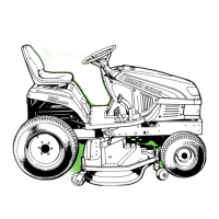
Fig. 3-108
• Install the idle gear.
Apply engine oil to the bore of the gear in ad-
vance.
Align respective timing marks with those of other
gears.
Fig. 3-109
• Installation of the injection pump
Tighten the bolts to the specified torque in se-
quence as shown in the figure.
Specified torque 0.8±0.2 kgf·m
Note:
Remember to install adjusting shims.