DAILY 4x4 ‒ GUIDELINES FOR BODYBUILDERS
ELECTRONIC SUB-SYSTEMS
5.2 BODYBUILDER CONNECTORS
13
– Printed 692.68.999 – 3 Ed. - Base 08-2020
230830
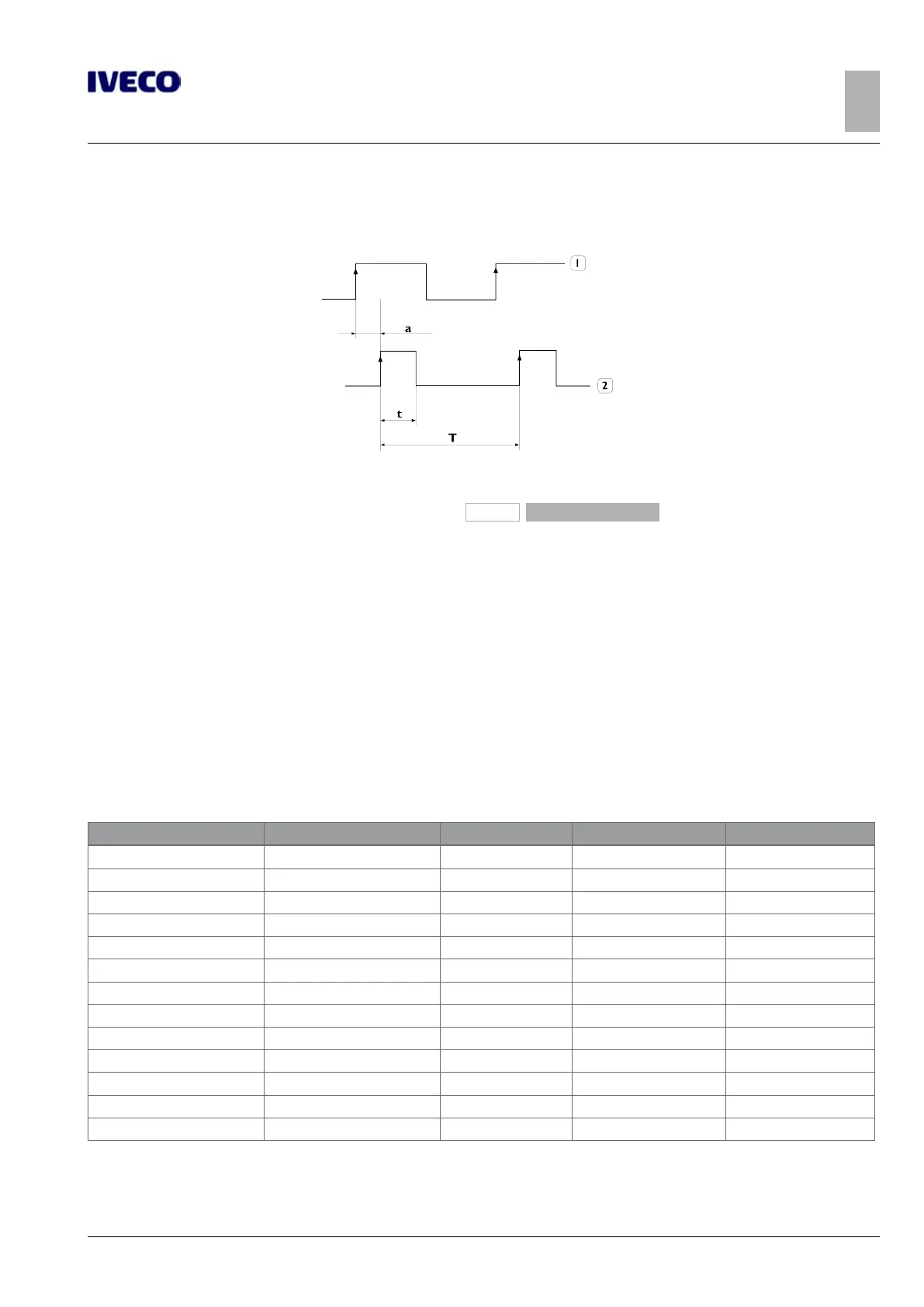
Figure 9
1. Speed signal (terminal B3) of the movement sensor fitted
on the reduction unit
2. Temporal diagram and form of the pulse speed signal
(terminal B7) from tachograph
a. Pulse delay: max 40 μs
±
10 μs jitter
(8)
Rpm signal
The rpm signal is a square wave.
The characteristics of the rpm signal are:
● 4 pulses for each revolution of the crankshaft;
● frequency field 0
–
400 Hz (corresponding to 0
–
6000 rpm);
● duty-cycle fixed at 50%.
Table 5.5- Characteristics of engine speed signal F1C Euro VI
Characteristics Condition Minimum Maximum Unit of measurement
C_EMI 3.76 5.64 nF
C_IO 3.76 6.14 nF
I_Out 2.2 A
I_Out_SC 4 A
I_Leak_Off 20
μA
I_Out_Diag 980
μA
V_OC 3.23 3.77 V
V_THR 4.7 5.4 V
V_Out_Low 1.76 V
R_ON 800 mΩ
E_Clamp 4 mJ
V_Out_Clamp 60 V
R_Load_Diag 4.69 kΩ
Legend:
● C_EMI: EMI capacity at the connector terminals

 Loading...