6
DAILY 4x4 ‒ GUIDELINES FOR BODYBUILDERS
EXPANSION MODULE
7.2 WIRING DIAGRAM
– Printed 692.68.999 – 3 Ed. - Base 08-2020
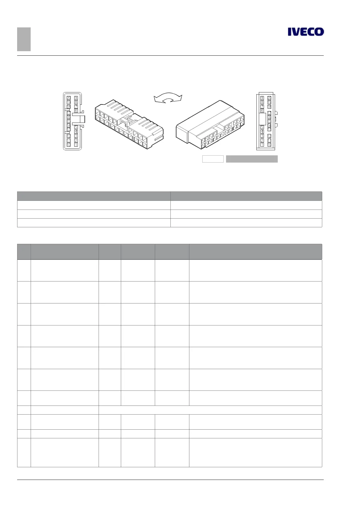
7.2.1 20-way EM connector, black (61071B)
101564
Figure 2
Existing part on vehicle (male) Counterpart to be coupled (female)
Table 7.5
Code Description
500314820 EZ Male contact for 0.35 to 0.5 mm² cable
500314824 EZ Male contact for 0.75 to 1.5 mm² cable
504005092 EZ Male contact for 2.5 mm² cable
Table 7.6 - Basic functions of connector 61071B
Pin Description
Cable
code
Signal
Connected
to
Remarks
1 Right stop light 9131
Output
1.5 A
EM X1/1
(1)
+12 V = stop light activated
No signal = stop light not activated
2 Right turn indicator 6985
Output
1.5 A
EM X1/3
(1)
+12 V = turn indicator activated
No signal = turn indicator not activated
3 Left stop light 9132
Output
1.5 A
EM X1/4
(1)
+12 V = stop light activated
No signal = stop light not activated
4 Left turn indicator light 6986
Output
1.5 A
EM X1/8
(1)
+12 V = turn indicator activated
No signal = turn indicator not activated
5
PTO 2 Solenoid /
CS: Additional light 2
CS: Blue light 2
9123
Output
1.5 A
EM X1/6
(1) (2)
12 V = PTO engaged activation
0 V = PTO disengaged activation
6
Reserved /
CS: Additional light 1
CS: Blue light 1
9995 3 A EM X1/7
(1) (2) (3)
12 V = Light activated
0 V = Light deactivated
7 PTO 2 feedback 6132
Input
5 mA
EM X3/9 Connection to ground to read PTO2 Feedback
8 Reserved
9 PTO 2 pressure switch 0392
Input
5 mA
EM X3/12
Connect to ground if active
It can be used to allow PTO engagement by the Bodybuilder
10 Reserved 0393 EM X3/16
11 Run-Lock switch 0132
Input
5 mA
EM X3/6
(1) (4)
Critical for Safety, see the Warning note
Ground = RunLock activation
Open wire = no action

 Loading...