DAILY 4x4 ‒ GUIDELINES FOR BODYBUILDERS
APPLICATIONS OF SUPERSTRUCTURES
3.2 ELEMENTS MAKING UP THE SUBFRAME
7
– Printed 692.68.999 – 3 Ed. - Base 08-2020
When the connection between the chassis and the subframe is such as to ensure the transmission of the shear stresses (connection
with plates), in checking the stresses at the two ends of the individual section, the new neutral axis has to be defined on the basis of
the different elastic modulus of the two materials.
3.2 ELEMENTS MAKING UP THE SUBFRAME
3.2.1 Longitudinal sections
The side members of the added structure must be continuous, extended as much as possible toward the front of the vehicle and
towards the rear area of the front spring support; in addition, they must rest on the chassis and not on the brackets.
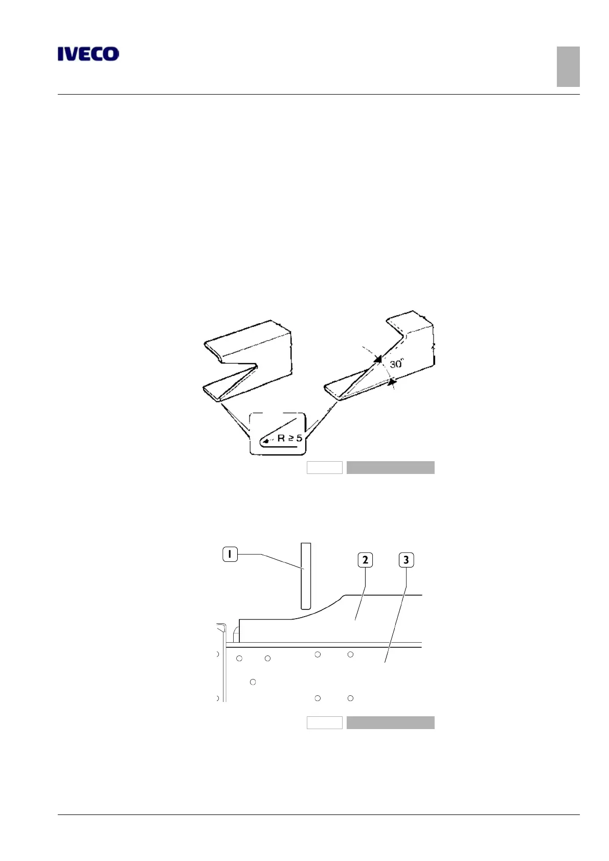
In order to achieve a gradual reduction of the resistant section, the front ends of the profile must be tapered in height with an
angle not exceeding 30°, or another form of equivalent tapering (see Figure 2); the front end in contact with the chassis must be
properly coupled, with min. radius of 5 mm.
91136
Figure 1
If the components (1) of the cab rear suspension do not allow the passage of the entire profile, this can be achieved as shown in
Figure 3. This may require verification of the minimum resistant section when there are high front bending moments and may also
require fixing to the chassis side member (3) at a distance of no more than 250 mm from the front end of the subframe (2).
262152
Figure 2
The shape of the profile section is defined taking into account the function of the subframe and the type of overlying structure.
Open C profiles are advisable when the subframe needs to adapt to the vehicle chassis and boxed sections when greater stiffness
of the assembly is required.
Care should be taken to achieve a gradual transition from the boxed section to the open section, as in the examples in Figure 4.

 Loading...