8
DAILY 4x4 ‒ GUIDELINES FOR BODYBUILDERS
EXPANSION MODULE
7.2 WIRING DIAGRAM
– Printed 692.68.999 – 3 Ed. - Base 08-2020
▶ The functions related to the PTO are not available.
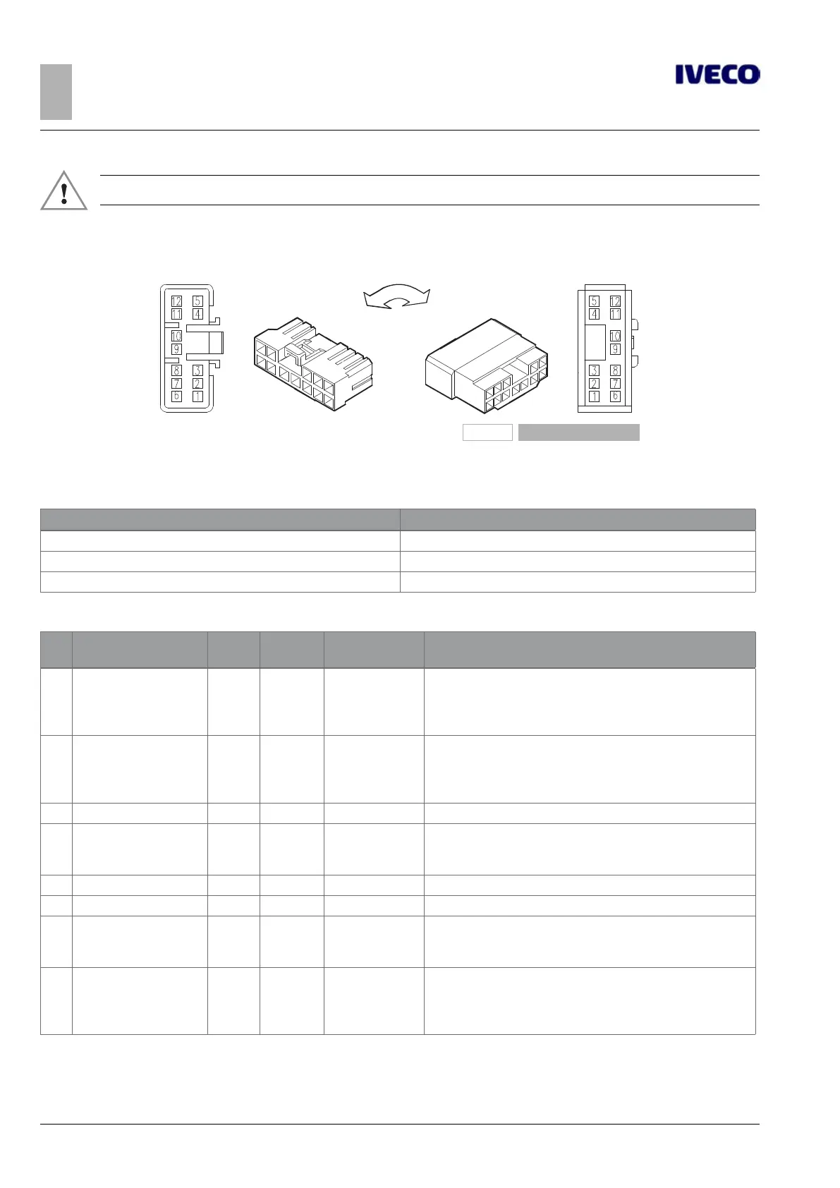
7.2.2 12-way EM connector, black (72075B)
101554
Figure 3
Existing part on vehicle (male) Counterpart to be coupled (female)
Table 7.7
Code Description
500314820 EZ Male contact for 0.35 to 0.5 mm² cable
500314824 EZ Male contact for 0.75 to 1.5 mm² cable
504005092 EZ Male contact for 2.5 mm² cable
Table 7.8 - Basic functions of connector 72075B
Pin Description
Cable
code
Signal Connected to Remarks
1 Right low-beam light relay 6988
Output
1 A
EM X4/2
To be enabled via TeleService
If enabled the PTO / ISC stored speed is not available
+12 V = low beams activated
No signal = low beams not activated
2 Left low-beam light relay 6989
Output
1 A
EM X4/3
To be enabled via TeleService
If enabled the PTO / ISC stored speed is not available
+12 V = low beams activated
No signal = low beams not activated
3 Reserved 0996 EM X4/6
4 Alarm command 5981
Output
5 mA
EM X4/14
Possible reconfiguration via Customer Service (CS)
+12 V = alarm function activation
0 V = no action
5 Reserved 5982 EM X4/15
6 Reserved 5991 EM X4/16
7 Engine stop control 6990
Output
1 A
EM X4/21
Output wired to ST 61071A / Pin 2
+12 V = engine stop activation
Open wire = no action
8 Side light 10W 6991
Output
1 A
EM X4/22
Reconfiguration via CS possible
If enabled ISC Memo / PTO stored speed is not available
+12 V = side light activated
No signal = side light not activated

 Loading...