DAILY 4x4 ‒ GUIDELINES FOR BODYBUILDERS
APPLICATIONS OF SUPERSTRUCTURES
3.7 INSTALLATION OF TANKS AND LOOSE MATERIAL CONTAINERS
17
– Printed 692.68.999 – 3 Ed. - Base 08-2020
3.7 INSTALLATION OF TANKS AND LOOSE MATERIAL CONTAINERS
3.7.1 Installation with a subframe
The installation of tanks and containers is carried out, as a rule, using a suitable subframe.
The approximate dimensions of the profile to be used for the subframe are shown in Table 3.5.
Table 3.5
Models Wheelbase [mm]
Minimum reinforcing profile
Section modulus W
X
[cm
3
] Dimensions [mm]
All 3080, 3480, 3780, 4175 21 80x60x5
Note
For the dimensions of the profiles see Table 3.2.
The assembly of tanks, or stiff torsional structures in general, must ensure sufficient and gradual flexibility of the chassis, in order to
avoid high stress areas.
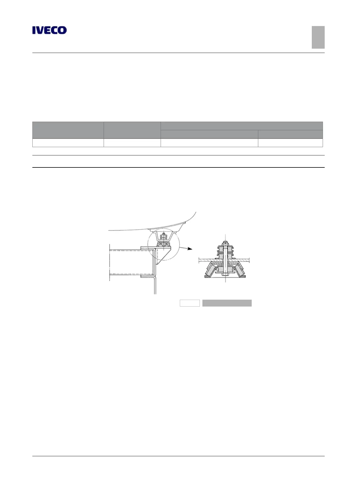
The use of flexible parts is recommended for the connections between the cistern body and the subframe (see Figure 12) in the
front section while rigid supports resistant to the longitudinal and transverse forces are recommended at the rear.
193895a
Figure 12
As previously mentioned, the stiff connections positioned in correspondence with the rear suspension mounts are more suitable
for transmitting forces directly to the suspension elements; elastic connections are to be arranged near the front suspension rear
mount.
If this is not carried out, use suitably oversized longitudinal reinforcement sections compared to those shown in Table 3.5.
When defining elastic connections, consider the rigidity of the chassis in the area where the connections are to be applied and the
type of functions for which the vehicle is intended.

 Loading...