DAILY 4x4 ‒ GUIDELINES FOR BODYBUILDERS
ELECTRONIC SUB-SYSTEMS
5.8 MISCELLANEOUS
37
– Printed 692.68.999 – 3 Ed. - Base 08-2020
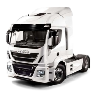
5.7.2 Passage of cables from cab interior to cab exterior
In the engine compartment, close to the brake-servo, through the five premade 10 mm holes in the bulkhead, it is possible the to
pass the electric cables from the cab to the engine compartment. Adequately seal the cable passage area to avoid passing fumes
from the engine compartment to the cab.
119355
Figure 38
▶ Any damage caused by failure to comply with procedure is not covered by warranty.
5.8 MISCELLANEOUS
5.8.1 Additional circuits
The additional circuits must be separated from the vehicle and protected by means of a specific fuse
As already seen in Chapter 5.4 ( ➠ Page 34) Paragraph "Precautions for work on the system", the cables used must be:
● of appropriate sizes and equipped with good original insulation;
● connected to the original system by means of tin joints equivalent to the original ones, protected with sheaths (not PVC) or
intubated in polyamide conduits of type 6;
● installed protections from shock, heat, rubbing with other components (in particular with the sharp edges of the bodywork);
● secured separately with insulated cable clamps (e.g. nylon) and at suitable intervals (approx. 200 mm).
The passage through crossbars and/or sections must provide special cable raceways or protections; it is not possible to drill the
chassis and/or the bodywork.
In case of external panels, use a specific sealant both on the cable and on the panel to prevent water, dust and fumes from infiltrat-
ing.
Where possible it shall also be provided a different cable path that transfers interference signals with high absorbed intensity (e.g.
electric motor, solenoid valves) and low absorbed intensity susceptible signals (e.g. sensors); for both must be remained a position-
ing as close as possible to the metallic structure of the vehicle.
Plug and terminal connections must be protected, resistant to weathering, and executed using components of the same type as
those utilised originally on the vehicle.
Use cables and fuses with the characteristics shown in the following table in accordance with the current draw:
Table 5.12- Use of cables and fuses according to the current drawn
Max. continuous current
(1)
[A] Cable cross-section [mm²] Fuse capacity
(2)
[A]
0–4 0.5 5
4–8 1 10

 Loading...