DAILY 4x4 ‒ GUIDELINES FOR BODYBUILDERS
CHASSIS INTERVENTIONS
2.2 DRILLS ON THE CHASSIS
7
– Printed 692.68.999 – 3 Ed. - Base 08-2020
2.1.4 Stresses on the chassis
The following stress value in static conditions cannot be exceeded for any reason whatsoever:
Note
Permitted static stress on the chassis: σ
adm
= 100 N/mm
2
In any case, respect any more restrictive limits placed by national standards.
Welding causes material property deterioration; therefore, when checking stresses in thermally altered zones, a resistance reduc-
tion of 15% must be accounted for.
2.2 DRILLS ON THE CHASSIS
Installation of auxiliary equipment onto the chassis must be done using the factory drilled holes whenever possible.
▶ It is strictly forbidden to drill holes into the side member flaps, with exception to what is indic-
ated in Chapter 3.3 - Paragraph "Choosing the type of connection".
When new holes must be made for specific applications (installation of shelves, corner shelves, etc.), these must be drilled into the
upright rib of the side member and must be thoroughly de-burred and bored.
2.2.1 Positioning and dimensions of the holes
The new holes must not be drilled into the areas subjected to greater stresses (such as spring supports) or where the side member
section varies.
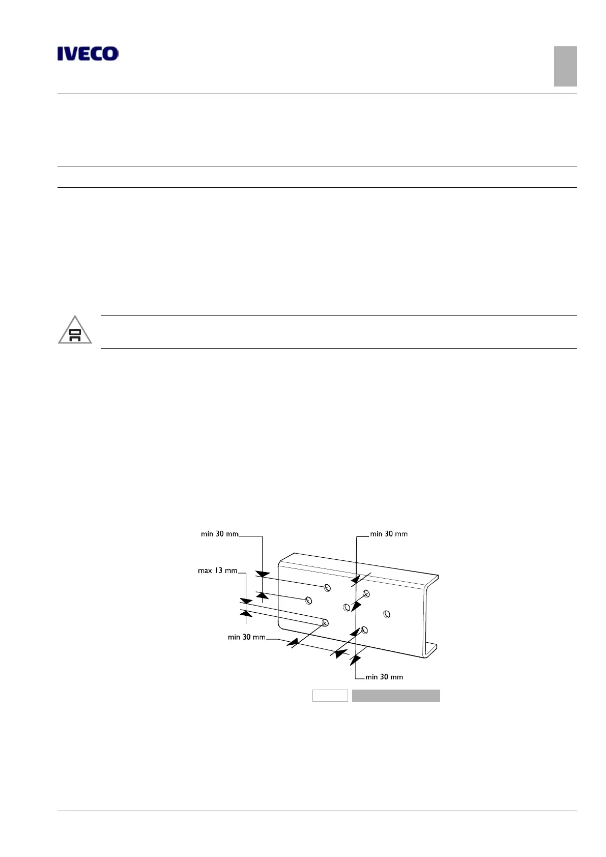
Hole diameter must be suited to sheet metal thickness but cannot exceed 13 mm (unless otherwise stated). The distance of the
axis of the holes from the edge of the side member must not be less than 30 mm; in the same way, the axes of holes must not be
less than 30 mm from each other or from other existing holes.
The holes must be offset as in Figure 2.
The original hole layout must be maintained when moving spring supports or crossbars.
102420
Figure 2

 Loading...