DAILY 4x4 ‒ GUIDELINES FOR BODYBUILDERS
EXPANSION MODULE
7.2 WIRING DIAGRAM
9
– Printed 692.68.999 – 3 Ed. - Base 08-2020
Pin Description
Cable
code
Signal Connected to Remarks
9 Scene lights relay 6992
Output
1 A
EM X4/23
Reconfiguration via CS possible
If enabled ISC Memo / PTO stored speed is not available
+12 V = scene light activated
No signal = scene light not activated
10 Reserved 5992 EM X4/38
11 Ground 0000 5 A
Fuse box and
distributor
Terminal 14/17
12
Vehicle with full CAN
operation
0980 3 A
N.D. with Additional Light configuration via CS
+12 V = Vehicle with full CAN operation
Ground = Vehicle with full CAN operation
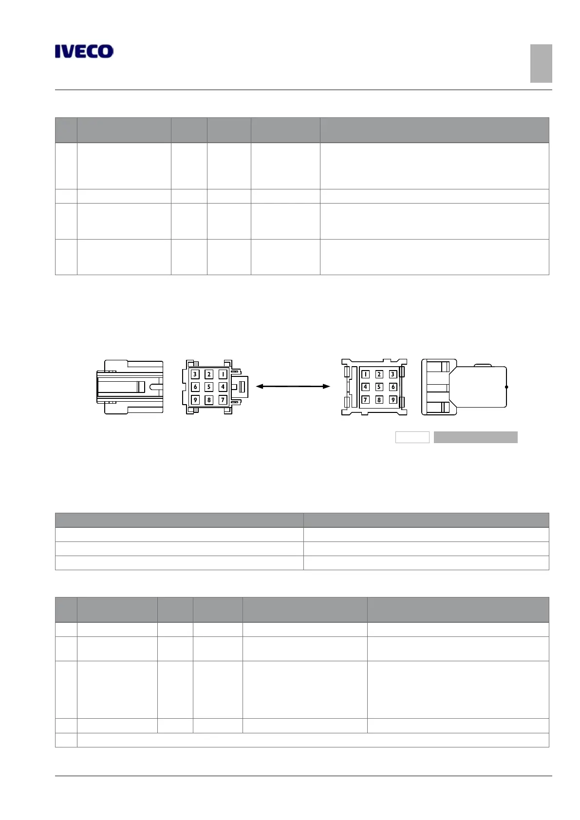
7.2.3 9-way EM connector, yellow (72071)
197421
Figure 4
Existing part on vehicle (male) Counterpart to be coupled (female)
This connector is only present in the case of EM installation with CAN open (opt 75979).
Table 7.9
Code Description
500314820 EZ Male contact for 0.35 to 0.5 mm² cable
500314824 EZ Male contact for 0.75 to 1.5 mm² cable
504005092 EZ Male contact for 2.5 mm² cable
Table 7.10 - Basic functions of connector 72071
Pin Description
Cable
code
Signal Connected to Remarks
1 K30 + 7772 TBD BCM G/10
2 K31 0000
Fuse box and distributor
Terminal 14/17
Ground
3 CO enabled CIA413 0975 0.5A EM X4/28
LSO activated with CO unit activation
(generally ~ 3sec after K15)
contact IVECO Customer Service for the adjustment
Open circuit = CANopen not operational
Ground = CANopen operational
4 Bodybuilders CAN H 6110 n.a. EM X4/18 CAN Open truck gateway, see CIA 413
5 Reserved

 Loading...