DAILY 4x4 ‒ GUIDELINES FOR BODYBUILDERS
ELECTRONIC SUB-SYSTEMS
5.4 ELECTRICAL SYSTEM
25
– Printed 692.68.999 – 3 Ed. - Base 08-2020
262233
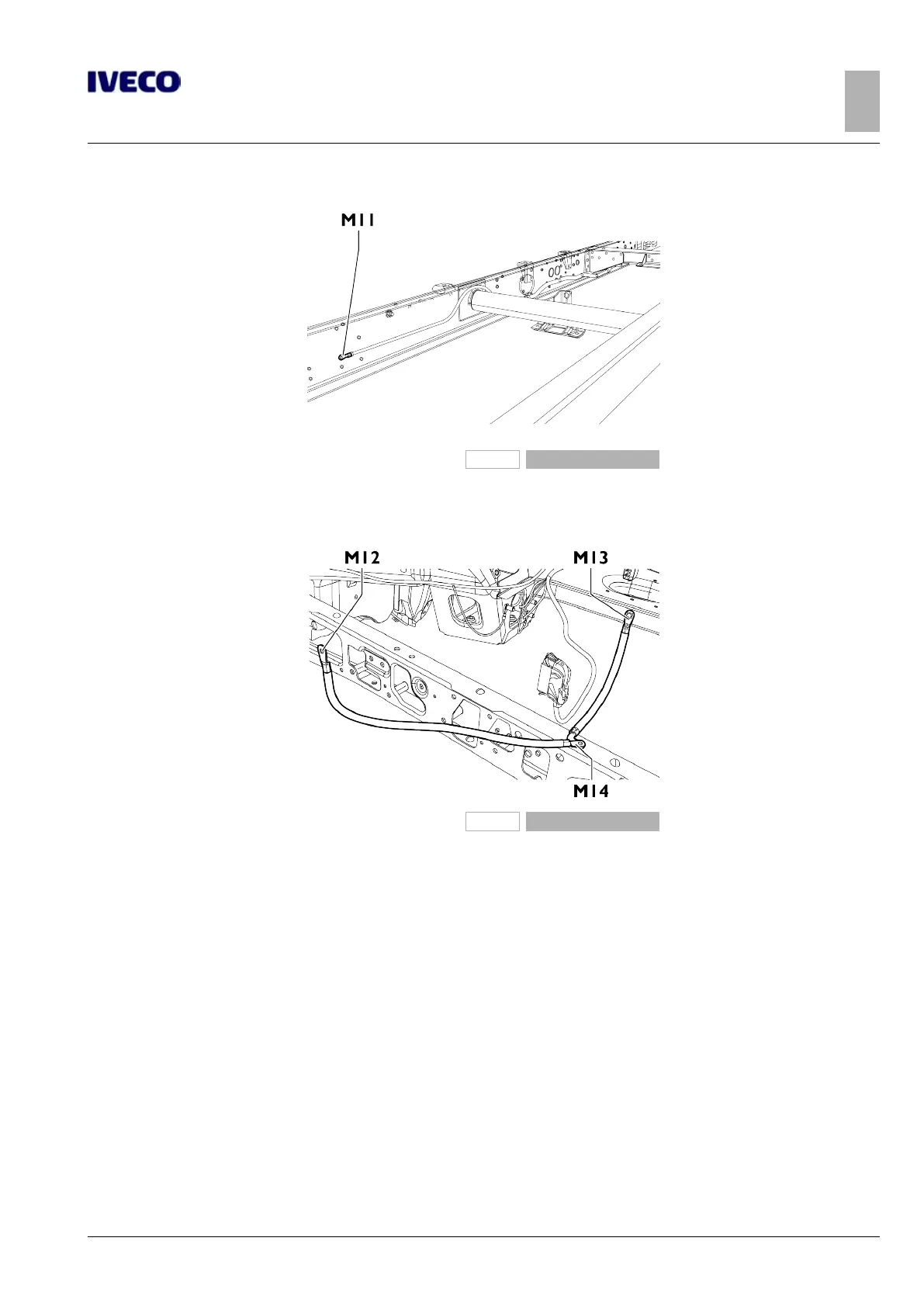
Figure 23
M11. Power ground on side member
262234
Figure 24
M12. Power ground on engine crankcase, left side
M13. Power ground, engine compartment, left side
M14. Power ground on side member
The negative leads connected to a ground point in the system must be as short as possible and must be connected to each other in
a "star" formation, while tightening must be done in an orderly and adequate manner.
As far as electronic components are concerned, the following instructions should be followed:
● electronic control units must be connected to the system ground when equipped with metal housings
● the negative cables of the electronic control units are to be connected to a system ground point, connected to the negative
terminal of the battery;
● the analogue grounds (sensors), while not being connected to the system ground/negative terminal of the battery, are to have
good conductivity. Consequently, particular care should be given to terminal parasitic resistances: oxidation, scratches, etc.;
● the metal braid of the shielded circuits must be in electrical contact only at the control unit side to which the signal is to be
sent
● In the presence of junction connectors the unshielded section d, near them, should be as short as possible;
● The cables must be routed in such a way as to be parallel to the reference plane, as close as possible to the chassis/body.

 Loading...