DAILY 4x4 ‒ GUIDELINES FOR BODYBUILDERS
APPLICATIONS OF SUPERSTRUCTURES
3.9 INSTALLATION OF TAIL LIFTS
23
– Printed 692.68.999 – 3 Ed. - Base 08-2020
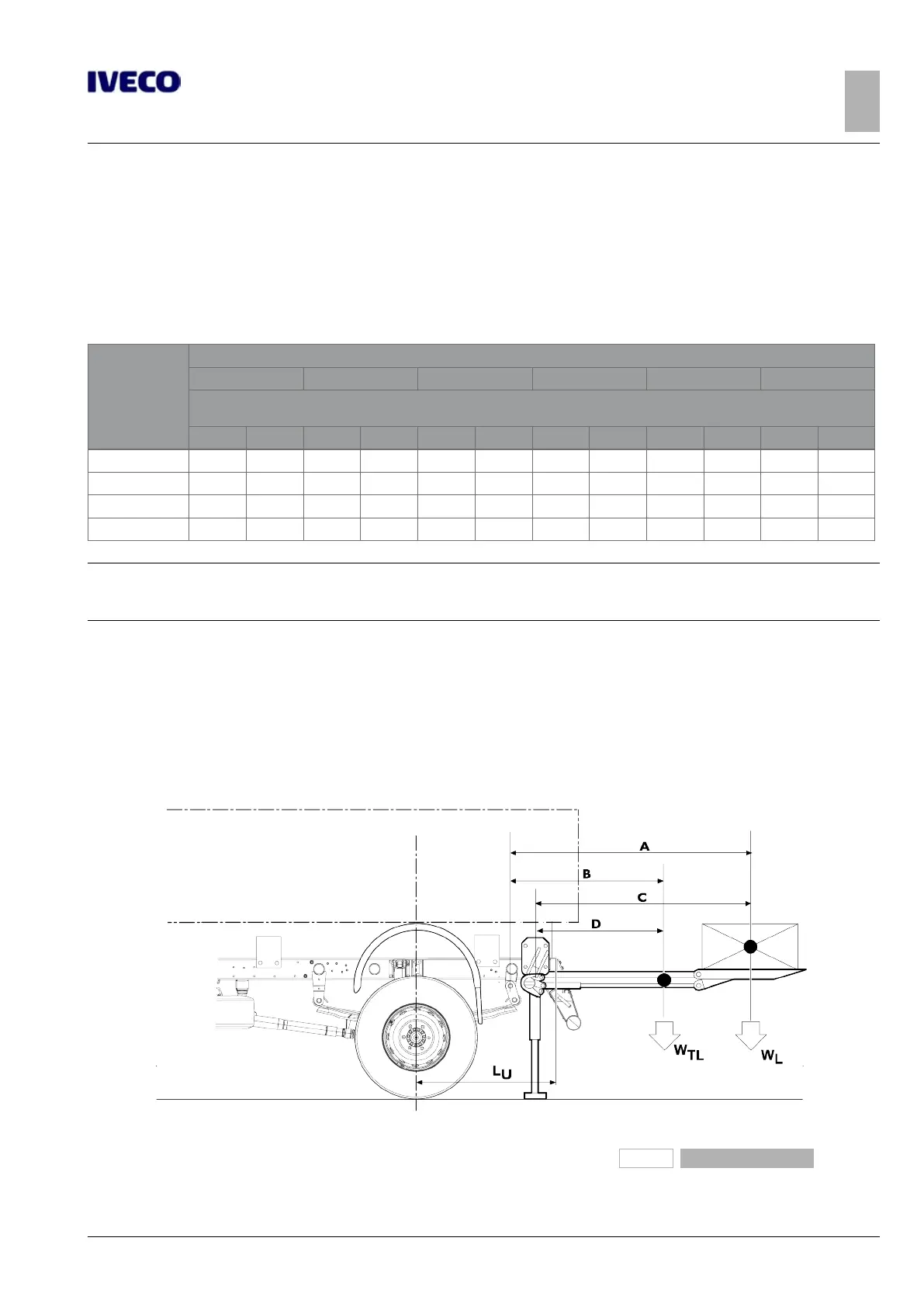
1. using Table 3.9, in the presence of trucks with rear overhangs as standard;
2. using the indications provided in Figure 17, with trucks with overhangs not as standard or specific tail lifts (for example, in
aluminium).
Case 1.
The bending moments on the chassis, depending on the capacity of the tail lifts, have average values which are already defined.
Table 3.9 - Installation of tail lifts (see Figure 17)
Wheelbase
[mm]
Tail lift capacity in kN (kg)
3 (300) 5 (500) 7.5 (750) 10 (1000) 12.5 (1250) 15 (1500)
Minimum value of the section modulus of the subframe section W
x
[cm
3
]
(1)
with yield point of the material equal to 360 N/mm
2
– S – S – S – S – S – S
3080 16 16 16 16 16 16 21 16
3480 16 16 16 16 21 16 26 21 36 26 50 38
3780 16 16 21 16 26 21 36 26 50 38 61 46
4175 16 16 21 16 36 26 50 38 61 46 71 56
Note
S = presence of stabilizers.
For the dimensions of the profiles see Table 3.2.
Case 2.
The bending moments on the chassis based on the load capacity of the tail lifts must be calculated on a case by case basis.
230047
Figure 17
L
U
= Rear overhang

 Loading...