Gb Fr
324501D revision07 - 63 -
De
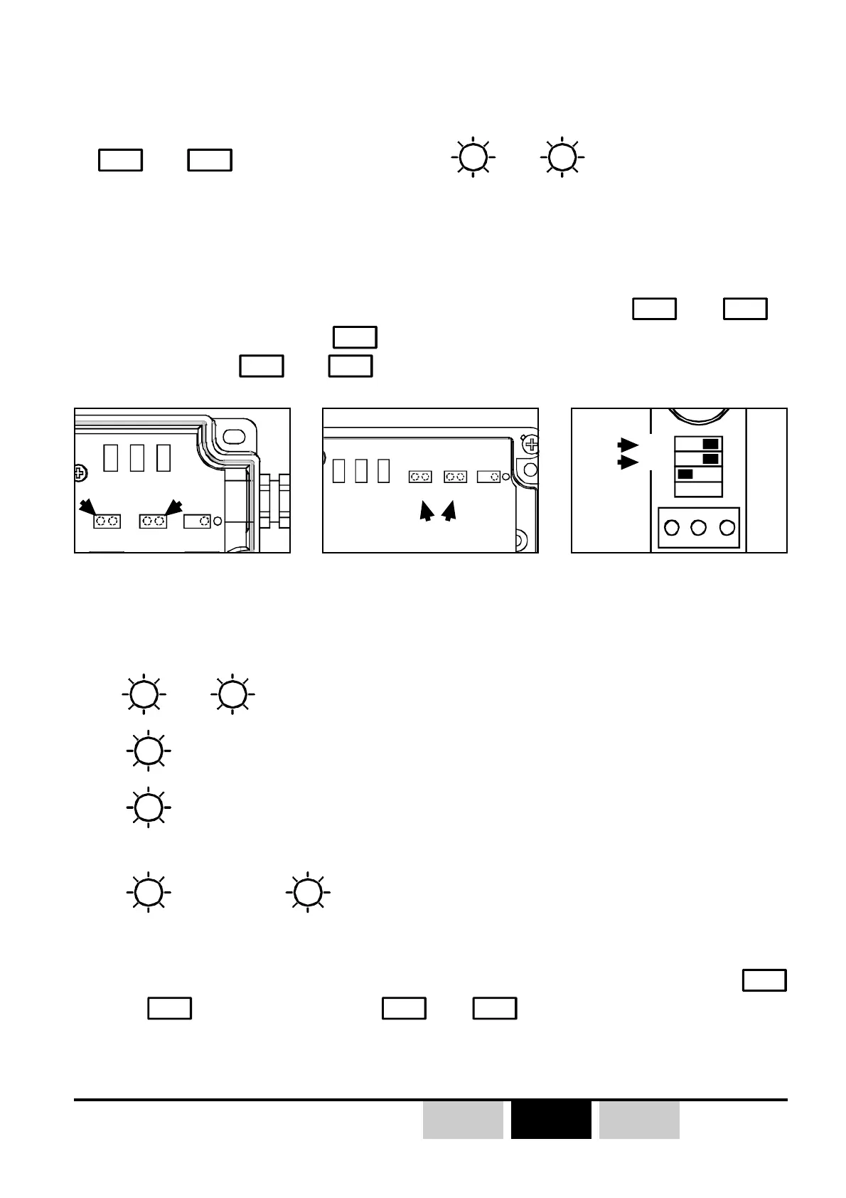
V1 V2 V3 JP3
JP1 JP2
V1 V2 V3
JP3
JP1 JP2
JP4
V1 V3 V2
JP3
JP1
ONOFF
JP2
3.8- Reading the current receiver radio channel
1- Switch off industrial receiver (ORRA or ORRS), the receiver on DIN rail
(ORRD) can remain power supplied during all the procedure.
2- For the ORRS and ORRA industrial receivers, place jumpers
JP1
and
JP2
in
the short-circuit position (
JP3
not short-circuited ), for the ORRD receiver, set
microswitches
JP1
and
JP2
to the «ON» position.
))
))
)
See list of available radio frequencies (radio channels) in appendix H.
ORRS receiver ORRA receiver ORRD receiver
3- "Industrial" type receivers (ORRA and ORRS): switch ON receivers.
4- -
V2
and
V3
LEDs indicate the current receiver radio channel number.
V2
(red) indicates the tens, «ON» = 10, «OFF» = 0
V3
(green) indicates the units by flashing.
Example :
V2
«OFF», and
V3
flashing 6 times, the current radio channel number is
«06» (433.600MHz)
5- Switch off industrial receiver (ORRS and ORRA) and remove jumpers
JP1
and
JP2
, or set microswitches
JP1
and
to the «OFF» position (ORRD).
z The reading of the receiver radio channel number is done from the receiver by
JP1
and
JP2
jumper/microswitch and
V2
and
V3
LEDs.