GbFr
- 64 - 324501D revision07
De
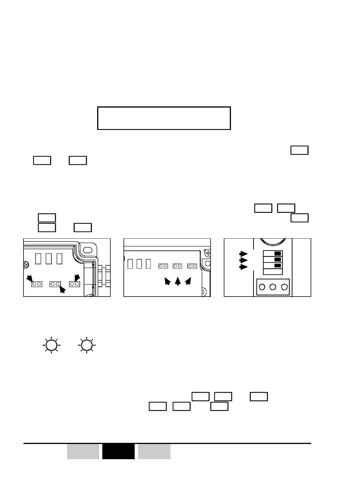
V1 V2 V3
JP1 JP2 JP3
V1 V2 V3
JP1 JP2 JP3
V1 V3 V2
JP1
ONOFF
JP2
JP3
JP4
3.9- Receiver parameter erasing procedure
This procedure has the effect :
- Erasing of all programmed transmitter(s) / receiver(s) associations,
- Erasing of all programmed interlockings,
- All relays operating mode turn by default mode : «Continuous make contact»
z The receiver parameters erasing procedure is done from the receiver by
JP1
,
JP2
and
JP3
jumpers/microswitches.
1- Switch off industrial receiver (ORRA or ORRS), the receiver on DIN rail (ORRD)
can remain power supplied during all the procedure.
2- For the ORRS and ORRA industrial receivers, place jumpers
JP1
,
JP2
and
JP3
in the short-circuit position, for the ORRD receiver, set microswitches
JP1
,
JP2
and
JP3
to the «ON» position.
))
))
)
Only the radio channel
setting is preserved
3- Switch ON «industrial» type receiver (ORRS and ORRA).
4- -
V2
and
V3
LEDs flash 5 times during the parameters erasing, then go off
(except on ORRD DIN rail receiver, indicator lights stop to blink for a few time
and re-start to blink 5 times etc...).
All the receivers parameters (except the radio channel setting) are erased.
5- Switch off the receiver and remove jumpers
,
JP2
and
JP3
(ORRS and
ORRA) , or set microswitches
JP1
,
JP2
and
JP3
to the «OFF» position
(ORRD) and proceed to a new programming.
ORRS receiver ORRA receiver ORRD receiver