GbFr
- 54 - 324501D revision07
De
JP2
JP4
JP1
V1 V3 V2
JP3
ONOFF
V1 V2 V3
JP1 JP2 JP3
V1 V2 V3
JP1 JP2 JP3
Once transmitter identity code was chosen and programmed, receiver relays must
be associated to transmitter buttons.
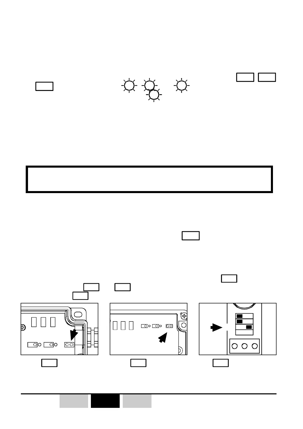
The receiver is equipped with 3 programming jumpers/microswitchies
JP1
,
JP2
and
JP3
and three LEDs with
V1
,
V2
and
which give indication to the
user during programming procedures (
V1
is switched ON continuously when
receiver is powered).
3.3.2- «Customized» transmitter buttond / receiver
relays association
The programming association procedure needs the
jumper/microswitch.
1- Switch off industrial receiver (ORRA or ORRS), the receiver on DIN rail
(ORRD) can remain power supplied during all the procedure.
2- For the ORRS and ORRA industrial receivers, place jumper
JP3
in the short-
circuit position (
JP1
and
JP2
not short-circuited ), for the ORRD receiver, set
microswitch
JP3
to the «ON» position.
))
))
)
In case of association programming error, the receiver memory can be
erased by following the procedure described in § 3.9
z Transmitter and receiver have to be on the same operating radio channel.
Requirements:
REMARK : each receiver relay can learn a maximum of :
- 10 different «button numbers + identity codes» for DIN Rail receivers
(ORRD) and «small model» industrial receivers (ORRS)
- 4 different «button numbers + identity codes» for the industrial «large
model» receivers (ORRA)
JP3
jumper
ORRS receiver
JP3
jumper
ORRA receiver
microswitch
ORRD receiver
3- Follow the procedure described by the algorithm in following page.