GbFr
- 52 - 324501D revision07
De
and
JP3
switches
on ORRD receiver
JP1
and
JP3
jumpers
on ORRA receiver
The programming association procedure needs the
and
JP3
receiver
jumper/microswitches.
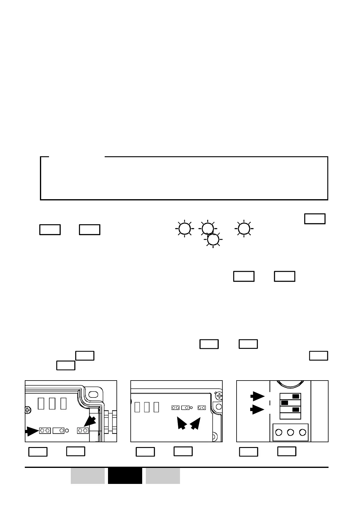
The receiver is equipped with 3 programming jumpers/microswitchies
JP1
,
JP2
and
JP3
and three LEDs with
V1
,
and
V3
which give indication
to the user during programming procedures (
is switched ON continuously
when receiver is powered).
V1 V2 V3
JP1
JP2
JP3
JP2
JP4
V1 V3 V2
JP3
ONOFF
JP1
V1 V2 V3
JP1
JP2
JP3
3.3.1- «FAST» transmitter buttons / receiver relays
association
This procedure is an auto-configuration of receiver relays.
The association of transmitter buttons (and its identity code) with receiver relays
is made in a automatic way as follows:
Button n°1 of the transmitter allocated to the relay n°1 of the receiver,
Button n°2 of the transmitter allocated to the relay n°2 of the receiver,
Button n°3 of the transmitter allocated to the relay n°3 of the receiver,
...etc
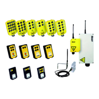
1- Switch off industrial receiver (ORRA or ORRS), the receiver on DIN rail
(ORRD) can remain power supplied during all the procedure.
2- For the ORRS and ORRA, place jumpers
and
in the short-circuit
position (
JP2
not short-circuited ), for ORRD receiver, set microswitches
JP1
and
JP3
to the «ON» position.
JP1
and
JP3
jumpers
on ORRS receiver
This programming procedure erases any buttons / relays associations,
interlockings and operating modes of previously programmed relays.
))
))
)
IMPORTANT