EasyManuals Logo

JCM DBV Series User Manual

JCM DBV Series
104 pages
To Next Page IconTo Next Page
To Previous Page IconTo Previous Page
Page #43 background imageLoading...
Page #43 background image
P/N 960-000180R_Rev. 1 {EDP #233427} © 2016, JAPAN CASH MACHINE CO., LTD.
2-19
Installation DBV® Series DBV-400 Banknote Validator Section 2
Standard Interface Circuit Schematics (Continued 6)
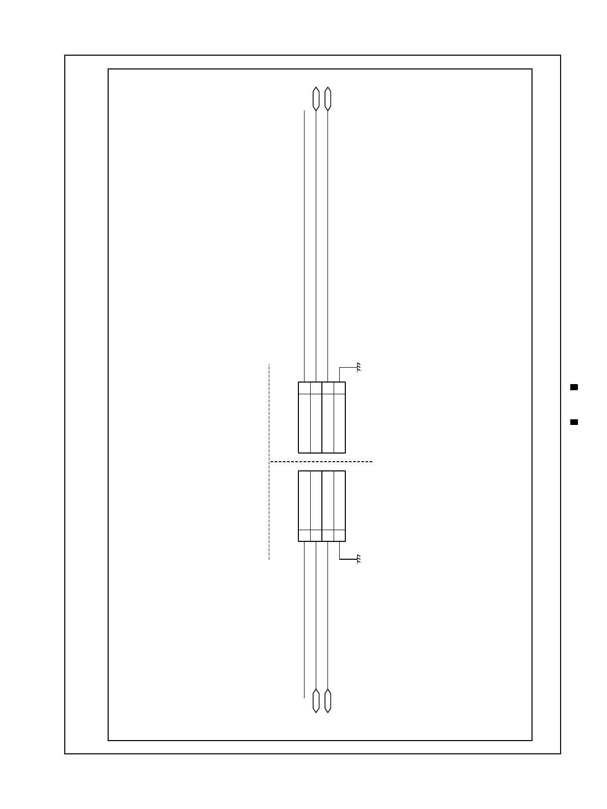
Figure 2-17 illustrates the DBV-400 USB Interface Schematic Diagram.
Figure 2-17 DBV-400 USB Interface Schematic Diagram
Vbus
Vbus
D-
D+
GND
1
2
3
4
Vbus
D-
D+
GND
1
2
3
4
Vbus
D -
D +
D -
D +
CONTROLLER SIDE
DBV-400 SIDE

Table of Contents

Other manuals for JCM DBV Series

Questions and Answers:

Question and Answer IconNeed help?

Do you have a question about the JCM DBV Series and is the answer not in the manual?

JCM DBV Series Specifications

General IconGeneral
BrandJCM
ModelDBV Series
CategoryBank Note Validator
LanguageEnglish

Related product manuals