NOTE: Figure 14 shows the boom panel of an EX2300-C switch when the switch is viewed
from the top. The internal components and top cover are not shown.
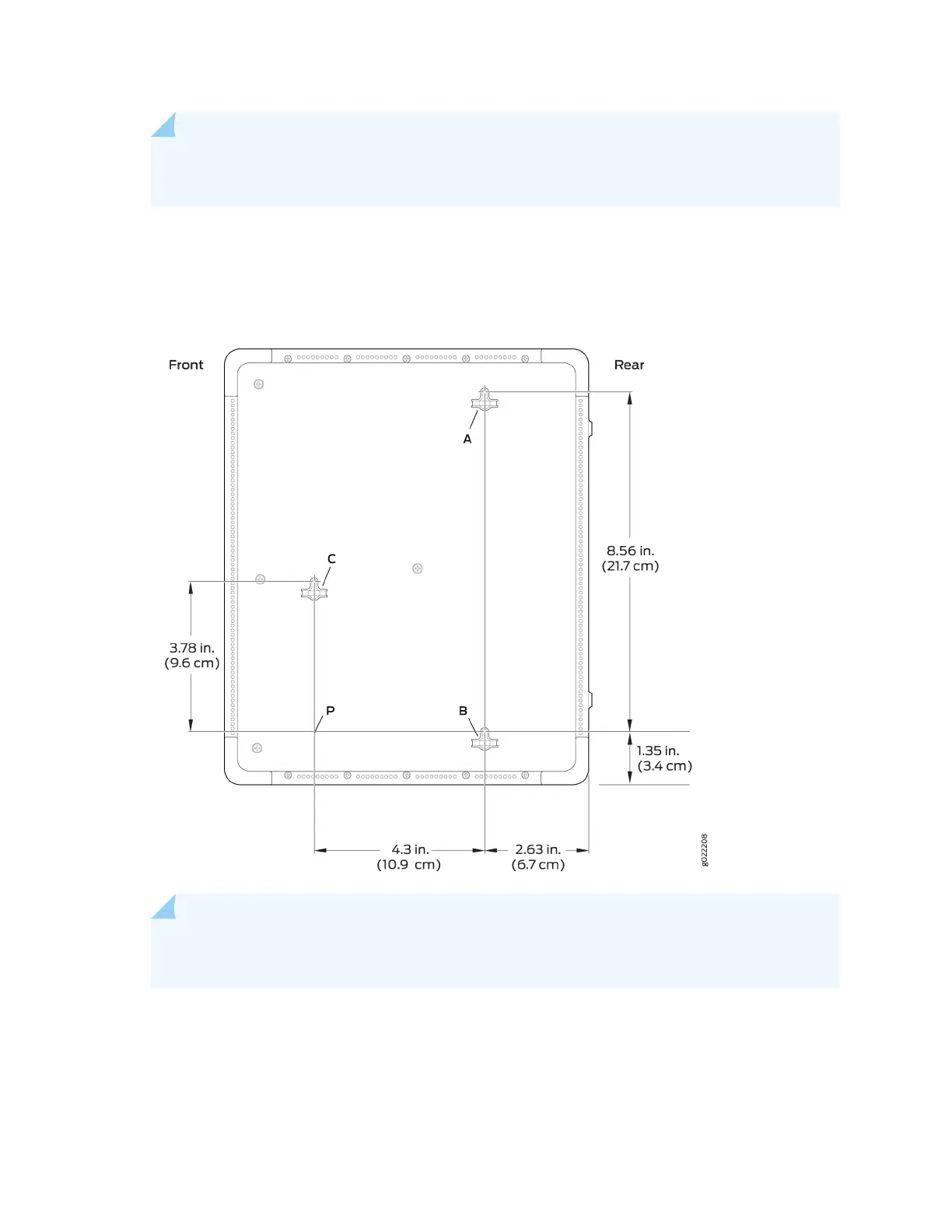
Figure 63: Measurements for Installing Mounng Screws for Mounng an EX2300-C Switch on a
Wall
NOTE: Tighten the screws only part way in, leaving about 1/4 in. (6 mm) distance between
the head of the screw and the wall.
a. Drill a hole A and install a mounng screw.
b. Drill a hole B at a distance of 8.56 in. (21.7 cm) on a plumb line from hole A and install a mounng
screw.
122
 Loading...


