c. Mark a point P at a distance of 4.3 in. (10.9 cm) on a level line to the right from hole B.
d. Drill a hole C at a distance of 3.78 in. (9.6 cm) on a level line to the top from point P and install a
mounng screw.
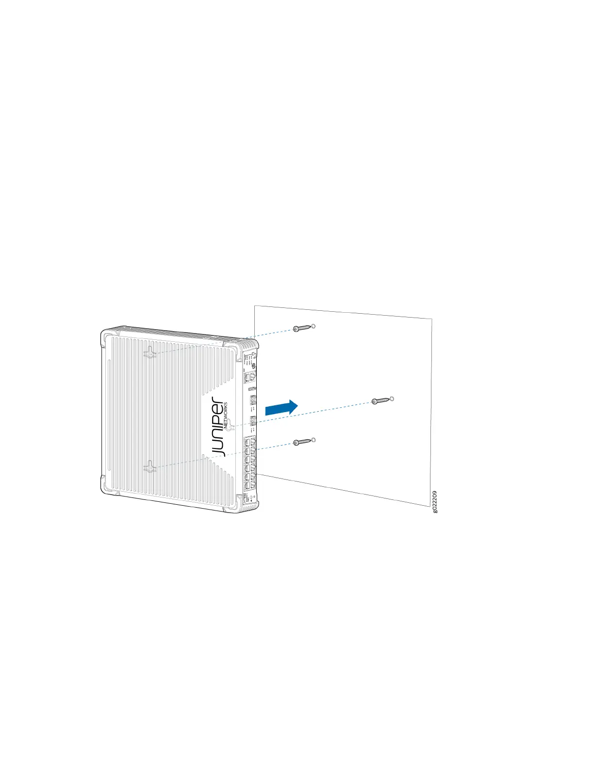
4. Place the switch against the wall such that the front panel of the switch faces to the right side and
the holes on the boom panel of the switch align with the mounng screw heads.
5. Slide the switch chassis to the le or right a bit so that the mounng screws are pushed into the
channels of the holes on the boom panel unl the switch rests rmly in place as shown in Figure 15.
6. Slide the switch chassis to the le or right a bit so that the mounng screws are pushed into the
channels of the holes on the boom panel unl the switch locks rmly in place as shown in Figure
15.
Figure 64: Mounng an EX2300-C Switch on a Wall
7. (Oponal) Aach the oponal standard cable lock to the security slot on the side of the switch:
a. Fasten the cable to a desk or a rack and set the lock to the unlocked posion.
123
 Loading...


