EasyManuals Logo

Juniper EX2300 Series Hardware Guide

Juniper EX2300 Series
314 pages
To Next Page IconTo Next Page
To Previous Page IconTo Previous Page
Page #135 background imageLoading...
Page #135 background image
NOTE: Tighten the screws only part way in, leaving about 1/4 in. (6 mm) distance between
the head of the screw and the wall.
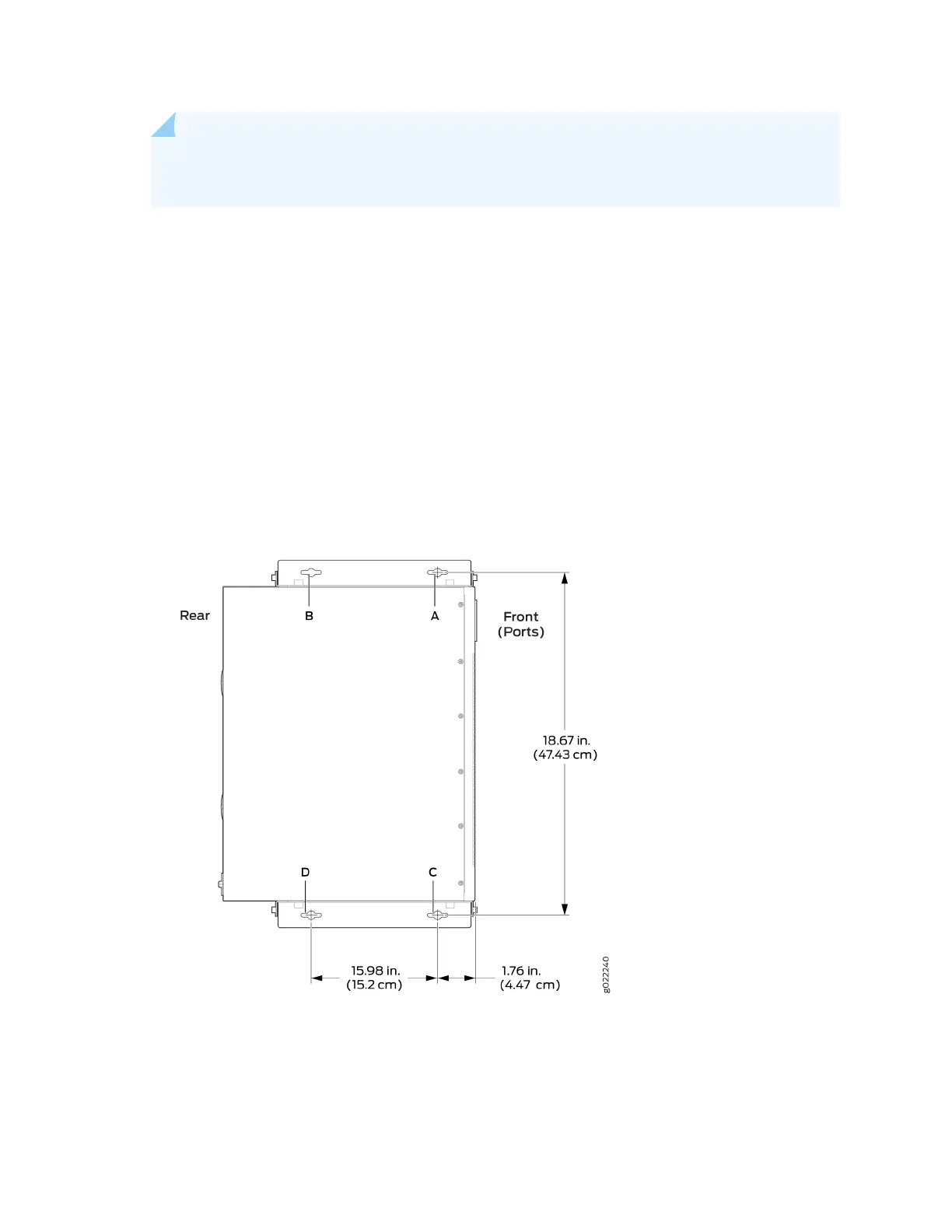
a. Drill a hole A and install a mounng screw.
b. Drill a hole B at a distance of 5.98 in. (15.2 cm) on a level line to the right from screw A and install
a mounng screw.
c. Drill a hole C at a distance of 18.67 in. (47.43 cm) on a plumb line down from screw A and install a
mounng screw.
d. Drill a hole D at a distance of 18.67 in. (47.43 cm) on a plumb line down from screw B and install a
mounng screw.
Figure 67: Measurements for Installing Mounng Screws to Mount an EX2300 Switch Except the
EX2300-24MP and EX2300-48MP Models and the EX2300-C Switch on a Wall
4. Place the switch against the wall such that the front panel of the switch faces to the right side and
the holes in the mounng brackets heads align with the mounng screw heads.
126

Table of Contents

Other manuals for Juniper EX2300 Series

Questions and Answers:

Question and Answer IconNeed help?

Do you have a question about the Juniper EX2300 Series and is the answer not in the manual?

Juniper EX2300 Series Specifications

General IconGeneral
SoftwareJunos OS
ModelEX2300
Ports24 or 48 10/100/1000BASE-T ports
Uplinks4 x 1GbE/10GbE SFP+/SFP uplinks
Power SupplyInternal or external power supply options
Rack Units1U
PoE/PoE+ PortsAvailable on some models (EX2300-C and EX2300)
Operating Temperature0° to 45°C
Input Voltage100 to 240 VAC
Layer 3 FeaturesRIP, OSPF, VRRP
Layer 2 FeaturesVLAN, STP, RSTP, MSTP, LACP
Security Features802.1X, DHCP snooping
ManagementCLI, Web UI, SNMP

Related product manuals