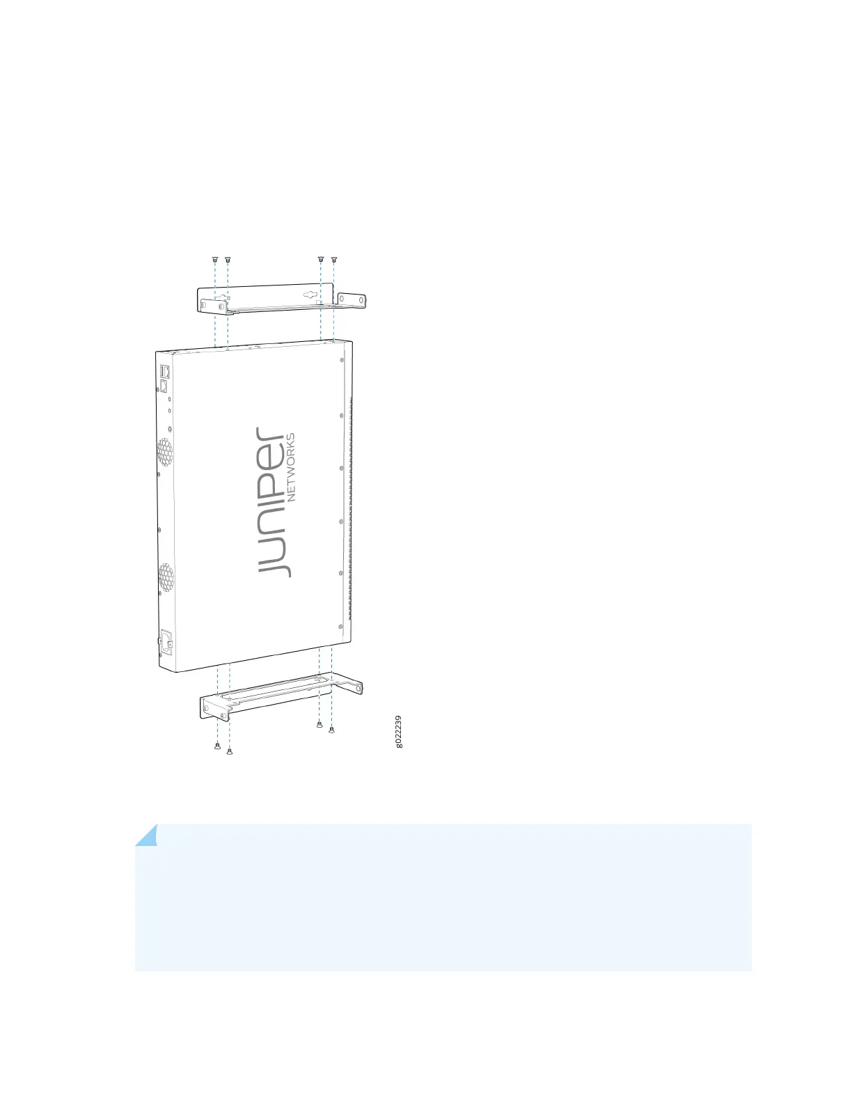
2. Aach the wall-mounng brackets to the sides of the chassis by using four wall-mounng bracket
screws, as shown in Figure 66 on page 125.
Figure 66: Aaching Wall-Mount Brackets to an EX2300 Switch Except the EX2300-24MP and
EX2300-48MP Models and the EX2300-C Switch
3. Install four mounng screws for the wall-mounng brackets on the wall as shown in Figure 67 on
page 126.
NOTE: Figure 67 on page 126 shows an EX2300 switch with 24 ports with PoE capability
when the switch is viewed from the top. The internal components and top cover are not
shown. The procedure to mount the switch on a wall and the distance between mounng
screws are the same for EX2300 switches with 24 ports with and without PoE capability
though the depth of the chassis of the switches with and without PoE capability are dierent.
125
 Loading...


