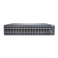
The QFX5240 Switch is a high-density, fixed-configuration device designed for use as end-of-row, leaf, or spine devices in an IP fabric architecture. It offers up to 64 800-Gigabit Ethernet (GbE) ports and is available in two models: the QFX5240-64OD and the QFX5240-64QD. The QFX5240-64OD features 64 800-Gbps octal small form factor pluggable (OSFP) ports and 2 10-Gbps SFP+ ports, while the QFX5240-64QD has 64 800-Gbps quad small form-factor pluggable - double density (QSFP-DD) ports and 2 10-Gbps SFP+ ports. With a bandwidth of 51.2 terabits per second (Tbps), the QFX5240 is optimized for shallow buffer platforms, making it suitable for the spine role in data center fabrics. The switches utilize the high-radix class TH5 - BCM78900 chip, a dedicated ASIC for high-bandwidth network switching. An Intel 4-core 2.2-GHz Ice Lake processor powers the control plane, running the Junos OS Evolved software, which is stored on two internal 480-GB Non-Volatile Memory Express (NVMe) solid-state drives (SSDs).
Technical Specifications:
- Models: QFX5240-64OD-AO (64x800GbE OSFP ports, 2x10GbE SFP+ ports) and QFX5240-64QD-AO (64x800GbE QSFP-DD ports, 2x10GbE SFP+ ports). Spare chassis models (QFX5240-64OD-CHAS, QFX5240-64QD-CHAS) are also available without PSUs and fans.
- Dimensions: 3.46 in. (8.78 cm) height, 19.03 in. (48.33 cm) width, 25.51 in. (65 cm) depth.
- Weight: 22 kgs (48.50 lbs) fully loaded without optics.
- Power Supply: Two 3000-W redundant AC power supply modules (PSMs) (QFX5240-PWR-AC-AO). Each PSM provides 12-V power, with an output power of 2.7 KW for an input voltage range of 200 VAC through 240 VAC. AC input current rating is 16 A maximum, and AC input line frequency is 50/60 Hz. PSMs support front-to-back airflow (airflow out or AFO) and offer 1+1 redundancy.
- Cooling System: Four front-to-back (airflow out or AFO) fan modules (QFX5240-2U-FANAO), each containing two 80 mm x 80 mm counter-rotating rotors. The cooling system offers N+1 redundancy at the rotor level. Fan speed varies based on internal component and ambient temperatures.
- Storage: Two internal 480-GB NVMe solid-state drives (SSDs) for Junos OS Evolved software image and configuration files.
- Optical Interfaces: Supports QSFP+, QSFP28, and QSFP-DD transceivers. Information on supported transceivers can be found using the Juniper Networks Hardware Compatibility Tool.
- Cabling: Multimode fiber crossover cables with MPO-12 (UPC/APC) connectors (OM3 or OM4) are used for 40-Gigabit Ethernet QSFP+, 100-Gigabit Ethernet QSFP28, and 400G (QDD-400G-DR4 and QDD-400G-SR4P2) transceivers.
- Management Ports: RJ-45 management port (MGMT) for out-of-band management and RJ-45 console port (CON) for serial interface. Default baud rate for the console port is 9600 baud. USB 2.0 Type-A and Type-C cables are also supported for console connections.
- USB Port: Supports RE-USB-1G-S (1GB), RE-USB-2G-S (2GB), and RE-USB-4G-S (4GB) USB flash drives.
- Environmental Tolerances:
- Altitude: Up to 6000 feet (1828.8 meters) with DAC cables; Sea level with optics (at 32° F through 104° F / 0° C through 40° C).
- Relative Humidity (operating): 5% through 90%, non-condensing.
- Temperature (operating): 32° F through 104° F (0° C through 40° C).
- Temperature (non-operating storage): –40° F through 158° F (–40° C through 70° C).
- Seismic: Designed to comply with Zone 4 earthquake requirements (NEBS GR-63-CORE, Issue 3).
Usage Features:
- Rack Installation: Designed for installation in four-post 19-inch racks using the QFX5240-2U-4PRMK rack mount kit. The rack mount kit allows for adjustable depth and supports the chassis evenly by all four corners.
- Initial Configuration: Performed through the console port using the CLI or zero-touch provisioning (ZTP). ZTP requires access to a DHCP server and a File Transfer Protocol (FTP), Hypertext Transfer Protocol (HTTP), or Trivial File Transfer Protocol (TFTP) server for software images and configuration files.
- Management: Managed using the Junos OS Evolved CLI via console and out-of-band management ports.
- LED Indicators:
- Network Port LEDs: Single RGB LED indicates link status, activity, or fault conditions (Unlit: Off/Link down/Transceiver not present; Green: 400/800-Gbps link established, with or without activity; Yellow: Link down due to other fault/transceiver hardware failure/port disabled; Red: Link down due to port/transceiver hardware failure).
- Chassis Status LEDs: Three LEDs (SYS, ALM, ID-LED) indicate system status. SYS (System status): Unlit (powered off/halted), Green (Junos OS Evolved loaded). ALM (Chassis alarm or fault): Unlit (no alarm), Red (major hardware fault), Amber (minor system level alarm). ID-LED (Identification): Unlit (beacon not enabled), Blue (blinking, beacon enabled).
- Management Port LEDs: Two LEDs indicate link status and link activity (Link activity: Unlit (no link/fault/down), Green (established, no activity), Blinking/Flickering (established, link activity); Status: Unlit (10 Mbps speed or link down), Green (1 Gbps speed), Green (100 Mbps speed)).
- Power Supply Module (PSM) LED: Bicolored amber and green LED indicates operating state (Off: no AC power; Solid green: on and functioning; Blinking green (0.5Hz): standby or other PSM on with 12 VSB; Blinking green (2Hz): redundant/offline mode; Solid amber: standby mode with OTP/critical event/fan failure).
- Fan Module LED: Bicolored status LED (Green: functioning normally; Red: faulty/malfunctioning; Unlit: input power failed).
- Grounding: Requires proper grounding to earth ground before connecting power to ensure safety and EMI compliance. A two-hole protective grounding terminal is provided on the chassis.
Maintenance Features:
- Field-Replaceable Units (FRUs): Power supply units and fan modules are hot-insertable and hot-removable, allowing replacement without powering off the switch or disrupting switching functions.
- Fan Module Replacement: Fan modules can be removed and installed while the switch is operating, but a failed module should be kept in place until a replacement is ready to maintain proper airflow.
- Power Supply Replacement: PSUs are hot-removable and hot-insertable. If only one PSU is installed, the switch must be powered off before removal.
- Solid-State Drive (SSD) Maintenance: The two 480-GB NVMe SSDs are preinstalled. The system must be shut down before removing or installing SSDs.
- Transceiver and Fiber Optic Cable Management: Transceivers are hot-removable and hot-insertable FRUs. Proper handling of fiber-optic cables is crucial to prevent damage, including avoiding sharp bends and ensuring clean connections. Rubber safety caps should be used to cover transceivers and cable connectors when not in use.
- Troubleshooting:
- Junos OS Evolved CLI: Primary tool for diagnosing hardware, routing protocols, and network connectivity issues.
- Alarms and LEDs: Visual indicators on the management panel and components help identify alarm conditions.
- Juniper Networks Technical Assistance Center (JTAC): Provides support for software problems or hardware components not covered in the documentation.
- Return Material Authorization (RMA): Procedures for obtaining an RMA number from JTAC for repair or replacement of defective components.
- Packing and Shipping: Guidelines for securely packing switches and individual components for shipment, including using antistatic bags and original packing materials. SSDs can be removed and disposed of according to security procedures before returning a chassis.