4.3 Machine function
Machine function (without options)
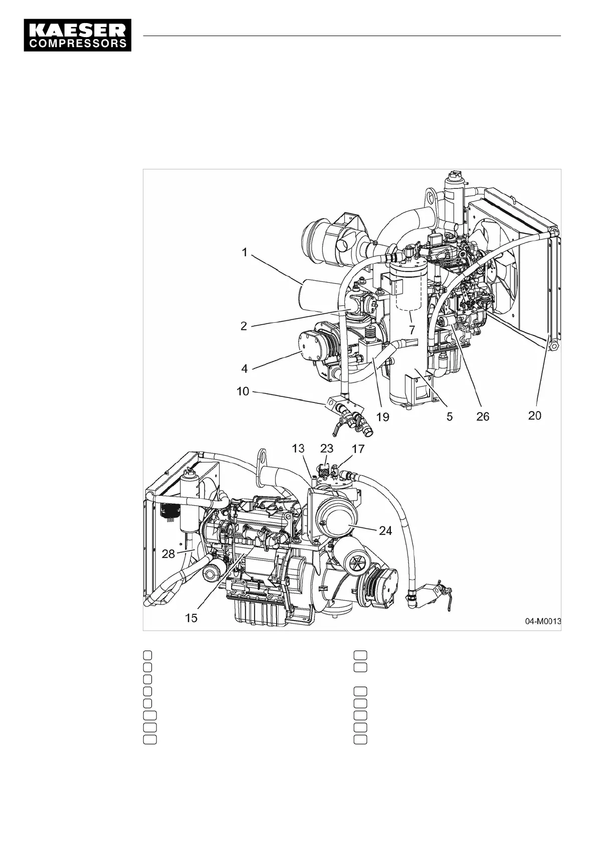
Item numbers correspond to the pipe and instrument flow diagram in chapter
13.2.
Fig. 4 General design
1 Compressor air filter
3 Inlet valve
4 Airend
5 Oil separator tank
7 Oil separator cartridge
10 Compressed air distributor
13 Pressure relief valve
15 Drive motor
17 Dirt trap
19 Thermostatic valve (oil temperature con‐
trol)
20 Oil cooler
23 Proportional controller
24 Engine air filter
26 Engine speed control cylinder
28 Fan
4 Design and Function
4.3 Machine function
28
SERVICE MANUAL Screw Compressor
M26 No.: 9_9446 01 USE