K990400 16 April 2008
Detail Screens
8-3
axial slice position view) and modify the criteria used to
generate the axial views (lower right).
• 3D Model View (lower left) shows a three-dimensional
representation of the anatomy of interest displayed on the
Implant Panning Screen. Dragging the cursor across the
image rotates the 3D image in the direction of the cursor.
Double right click-and-hold the mouse button horizontally
rotates the image. The mouse scroll wheel is active to scroll
through the slices.
• Cross Section Views (lower right) shows cross section
details of the anatomy of interest as specified on the axial
slice position view and the panoramic map view. The mouse
scroll wheel is active to scroll through the slices.
Patient position indicators are used on the Implant Planning Screen
to indicate the orientation of the displayed data. These are:
R = Right Side
P = Posterior
B = Buccal
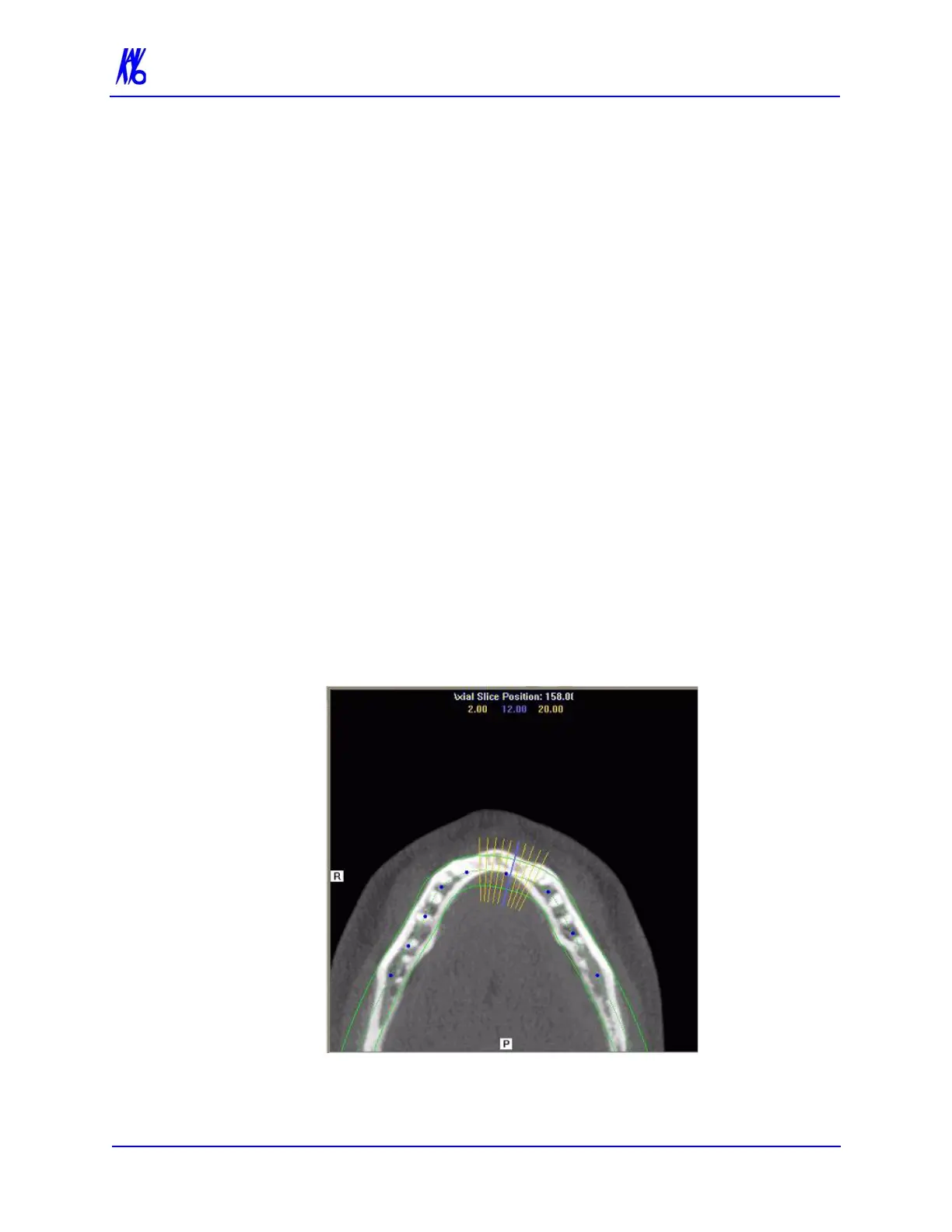
To use the Implant Planning Screen:
1. Click and drag the blue dots on the axial slice position view to
adjust the image displayed on the panoramic map view.