For that purpose, an initiator is connected to a digital input which generates a pulse at a xed round table posi-
tion. Whenever this pulse is recognised, the actual position must be equal to the position of the initiator. If this
is not the case, the actual position is set to the initiator position. The setpoint- and target position are corrected
by the same value as the actual position.
Example:
The drive rotates clockwise.
The initiator provides a signal at position 1000.
The drive starts at position 0.
The actual position (ru.54) at the time the edge of the initiator is 999.
The set point position (ru.56) is 1002, the target position is 5000 increments.
The value range round table (PS.39) is 10,000 increments.
The actual position is set to 1000, i.e., corrected by +1.
The set point position is set accordingly to 1003 and the target position to 5001.
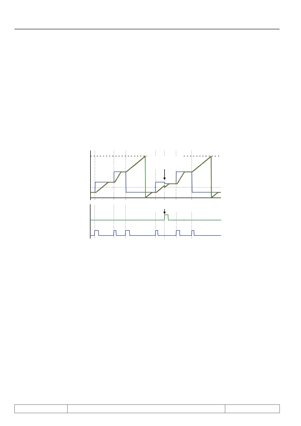
act. and set position =
ref.-point (PS.17)
target position adjusted
Start positioning
Set reference point
ru.61: target position
ru.65: Set position
ru.54: actual position
clockwise rotation → positive
edge
For the positioning for which corrections are made, the value of PS.24 "index/ position", therefore, does not
match ru.61 "target position" anymore, instead of the value 5000, positioning is done to 5001.
The next position is again approached corresponding to PS.24, i.e., the value of target position (ru.61) and
index / position (PS.24) match. Thereby, the error caused by the noninteger gear ratio is compensated.
Since the initiator signal is longer than one increment, the same point of the initiator must always be used for
the adjustment. Therefore, adjustments for clockwise direction of rotation is made as soon as the initiator is
reached (positive edge). For counter clockwise direction of rotation, adjustments are made when the initiator is
left (negative edge).
Example: The initiator signal is active from Position 5000 to 5500
To have the adjustment executed always at position 5000, adjustments must be executed at the positive edge
for clockwise rotation and at the negative edge for counter clockwise rotation.
Page 7.12 - 56 COMBIVERT F5-A, -E, -H © KEB, 2012-10
Posi- and synchronous operating

 Loading...

