Page 10.1 - 12 COMBIVERT F5-A, -E, -H © KEB, 2012-10
Network components
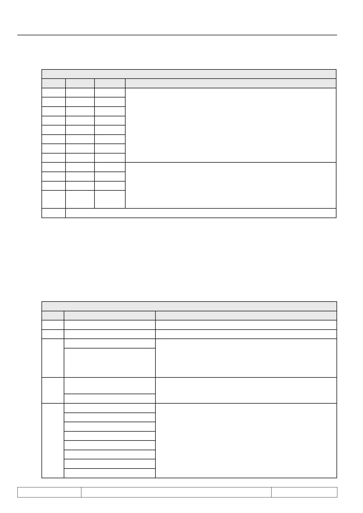
SY.41: Control word high
Bit Function Value Description
16 I1 1: I1
corresponding input is set via the control word instead via hardware input.
These bits are only effective if in di.01 „select signal source“ the bit for the
appropriate input is set. Then the OR operation of this bit with the appropriate
bits of parameter di.02 „digital input setting“ is valid.
17 I2 2: I2
18 I3 4: I3
19 I4 8: I4
20 IA 16: IA
21 IB 32: IB
22 IC 64: IC
23 Id 128: Id
24 O1 256: O1 appropriate output is set via the control word or via the switching conditions.
Output signals O1, O2, R1 and R2 (visible in parameter ru.80) are OR ope-
rated with the appropriate bits of the control word. The connection occurs
according di.42 „inverted outputs “(inverting level for the output signals) and
before they are switched to the hardware outputs with do.51 „hardware output
allocation“.
25 O2 512: O2
26 R1 1024: R1
27 R2 2048: R2
28...31 reserved
Control word long SY.43
The control word long (32 Bit) consists of SY.50 and SY.41.
Status word low SY.51
The actual state of the inverter can be read out with the status word.
SY.51: Control word low
Bit Value Description
0 1: ST 1= set control release (AND operation with di.01 bit 0)
1 2: Error Inverter is in error state
2
0: Stop The modulation is switched off at „stop“ and switched on at „start“.
Exception: if a positioning is stopped with bit 11 "abort" in the con-
trol word, "stop" is displayed in the status word, if the drive re-
aches speed 0 (even if modulation is still active). This exception
can be cancelled with bit 9 in parameter Pn.65 „special functions“
4: Start
3
0: Clockwise
rotation
Display of the actual direction of rotation
8: Counter-clockwise rotation
4...6
0: Set 0
Display of the actual parameter set
16: Set 1
32: Set 2
48: Set 3
64: Set 4
80: Set 5
96: Set 6
112: Set 7

 Loading...

