Network components
© KEB, 2012-10 COMBIVERT F5-A, -E, -H Page 10.1 - 13
10
7
128: Actual value = Setpoint
value
ru.07 „actual value display“ with a hysteresis of +/- LE.16 „freq./
speed hysteresis“ has the same value as ru.01 „set value display“
8 256: Fast stop Fast stop is active
9 512: HSP5 bus-synchronous Inverter in bus-synchronous operation
10
1024: Approach to reference
point completed
Approach to reference point was executed since the last power on
(or the position was validate otherwise)
11 2048: Position reached
Display that the position prole is completed and the drive is within
the range of “+/- PS.30 „target window“ near ru.61 „target position“
12, 13
0: Speed control
Display of the operating mode selected via control word
(only identical with the actual operating mode of the inverter, if in
PS.00 „pos/syn mode“ in bits 0...2 value „7: via control word“ is
programmed)
4096: Synchronous running
8192: positioning
12288: Contouring control
14
Posi or approach to reference
point active
Positioning or approach to reference point is active
15 internal limit
The speed setpoint value or any controller (e.g. current, ux, speed
or external PID controller) is in limitation (also in V/f characteristic
open-loop operation)
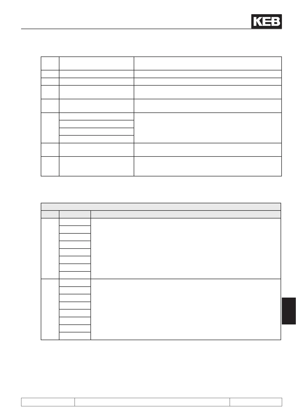
Status word high SY.42
The status word high is bit-coded designed as follows.
Sy.42 Status word high
Bit Value Explanation
0...7
1: I1
Display of the internal input terminal status (input terminals and software inputs after
the input processing block). Corresponds to the display in ru.22 „internal input state“
2: I2
4: I3
8: I4
16: IA
32: IB
64: IC
128: Id
8...15
256: O1
Display of the state of the output terminals and the software outputs (digital outputs
after the output proccessing block). Corresponds to the display in ru.25 „output
terminal state“
512: O2
1024: R1
2048: R2
4096: OA
8192: OB
16384: OC
32768: OD
It is necessary that the watchdogs are active at control via bus (operator and HSP5).

 Loading...